Fatigue and Plastic Collapse Analysis on Waste Heat Boiler
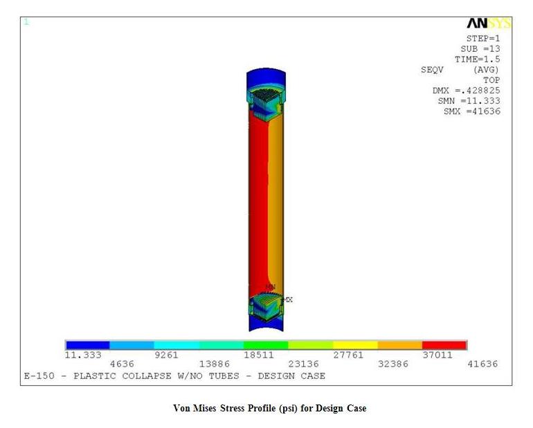
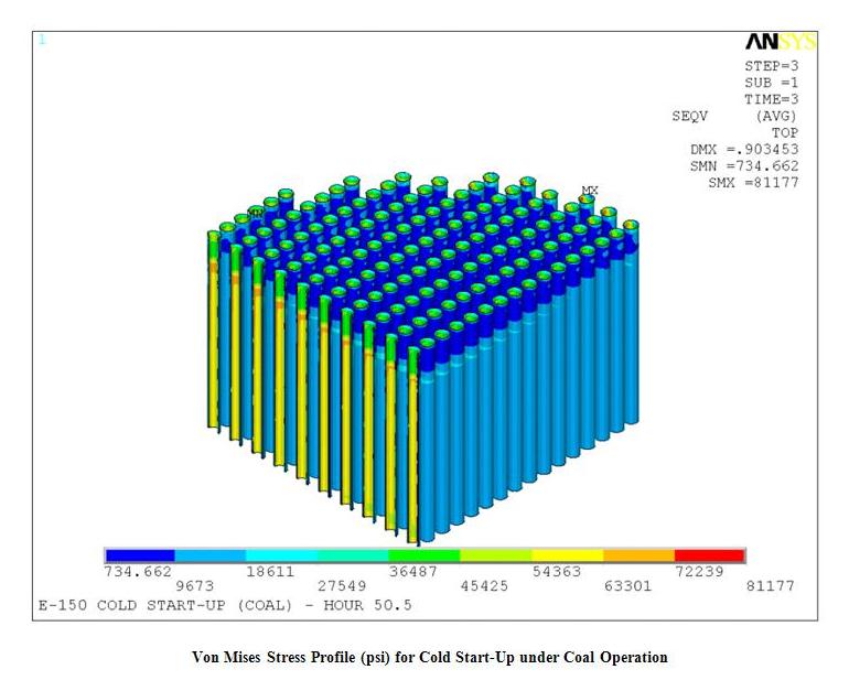
The scope of this project was to perform fatigue and plastic collapse analyses on a waste heat boiler that was used to cool raw syngas from the outlet of the gasifier. The thermal energy of the gas is used to produce High Pressure (HP) saturated steam on the shell side of the waste heat boiler.
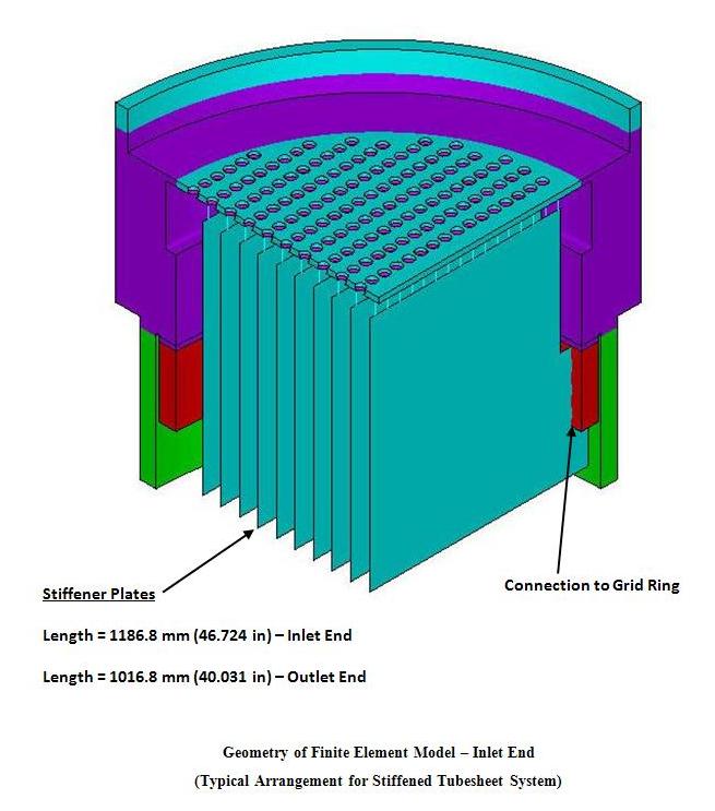
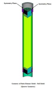
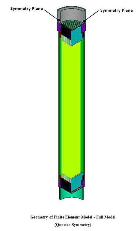
Fatigue Analysis: A Three-Dimensional (3D) Finite Element Model was developed to perform Finite Element Analysis (FEA) for the boiler. Fatigue analysis was performed to determine the permissible number of cycles remaining for the tubes which were to be salvaged.
Plastic Collapse Analysis: This analysis was a supplement for salvaging the boiler tubes. The analysis was performed to determine the safety of the waste heat boiler in the event that a tube, or tubes, would fail.
-

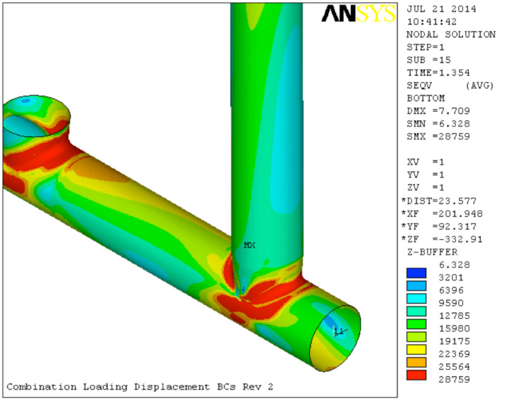
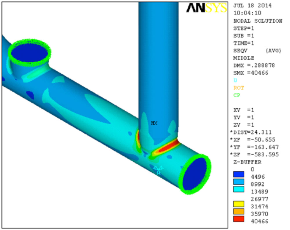
- Stresses2
-

- Stresses1
-
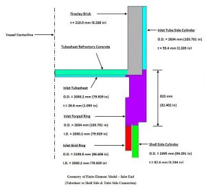
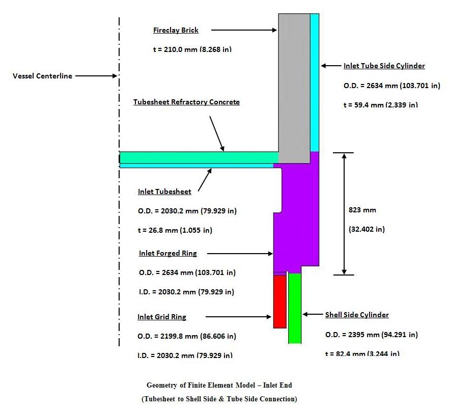
- Geometry3
-

- Geometry2
-
- Geometry1
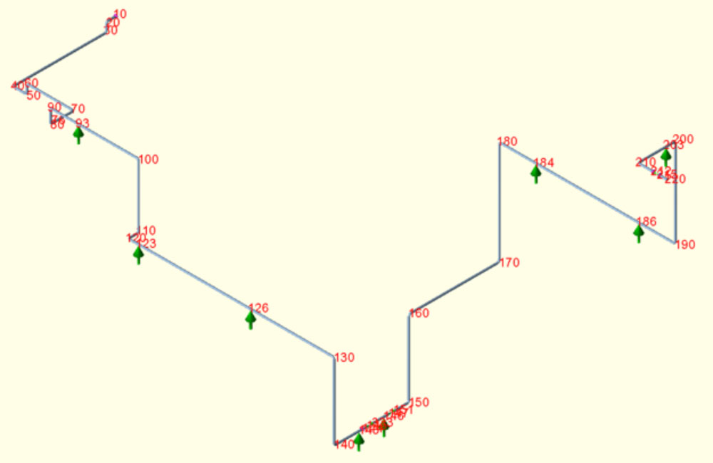
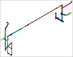
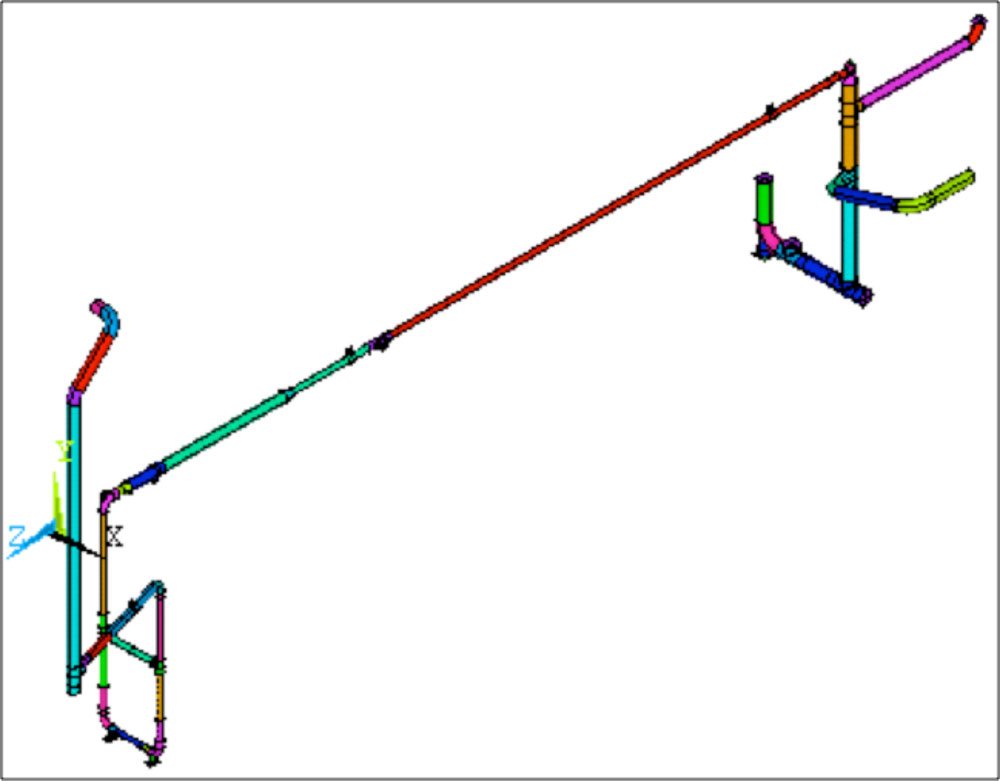
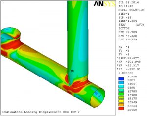
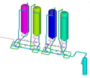
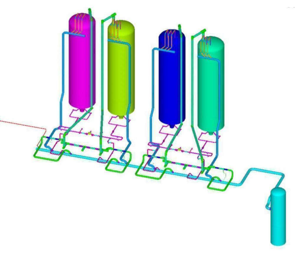
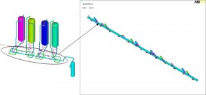
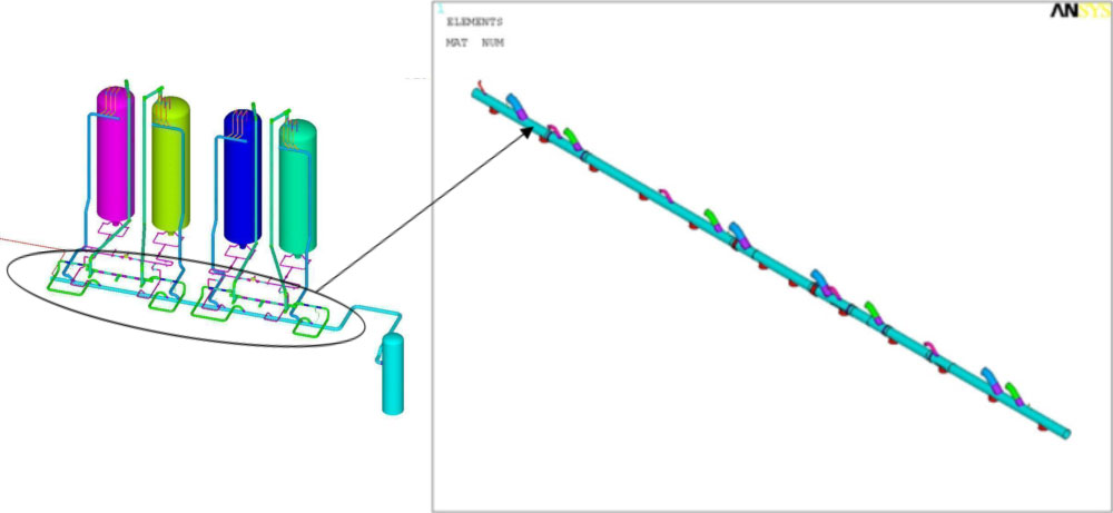
Flange Misalignment Analysis of Heat Exchangers and Piping System
Openso was requested to determine potential factors causing misalignment in a heat exchanger and associated piping system. The misalignment was determined to be caused by the thermal expansion and contraction of the piping system relative to the flanges of the heat exchangers. The accumulation of plastic strain, and therefore permanent deformation at weaker sections of the piping resulting from thermal expansion, was instrumental in the formation of the total misalignment.
-
- General Layout for the Piping System

-
- Total Misalignment in the Piping Flange to Pump Connection
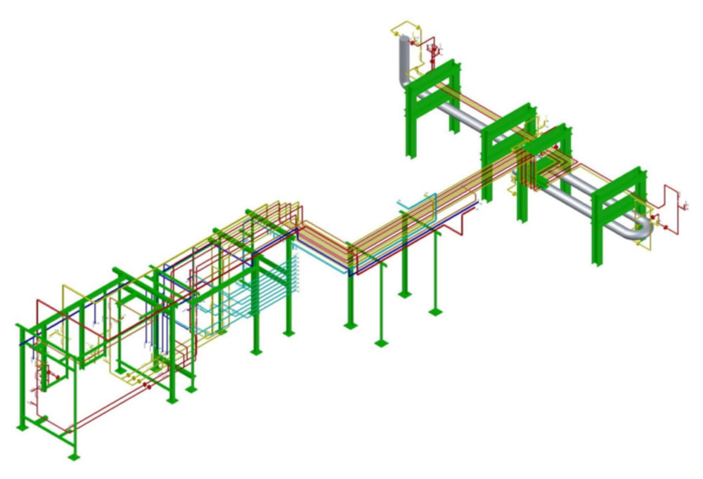
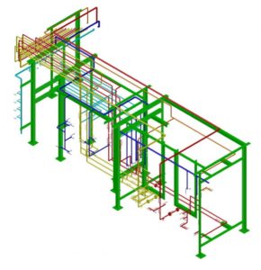
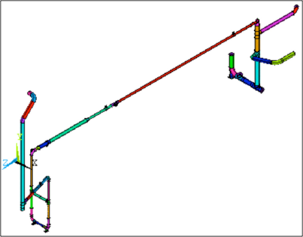
Field measurements, design, analysis, and Isometric Drawing Production for Expanding a Chlorine Abatement Unit
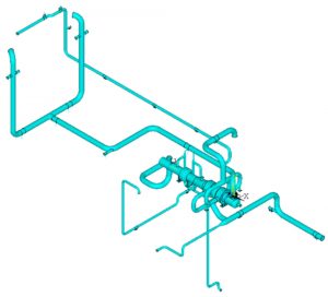
Field measurements were performed for a new chlorine abatement unit pipeline route in order to expand production for a chemical company. Initial pipe routing sketches for natural gas, hydrogen, chlorine, and nitrogen lines were modeled using AutoCAD Plant 3D. Pipe supports were also included in the 3D model for each pipeline from the customer interface point to end user. The routing information, types of valves, switches, instrumentation, and supports were included in the isometric drawings. Pipe stress analysis was performed based on ASME 31.3 to determine the adequacy of the supports using CAESAR-II.
-

- Chlorine Abatement Unit Model with Nitrogen, Natural Gas, Hydrogen, and Chlorine Pipe Routes with Valves, Instrumentations, and Supports
-

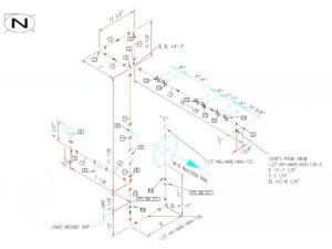
- Injection Ring Inlet of the Chlorine Abatement Unit
-
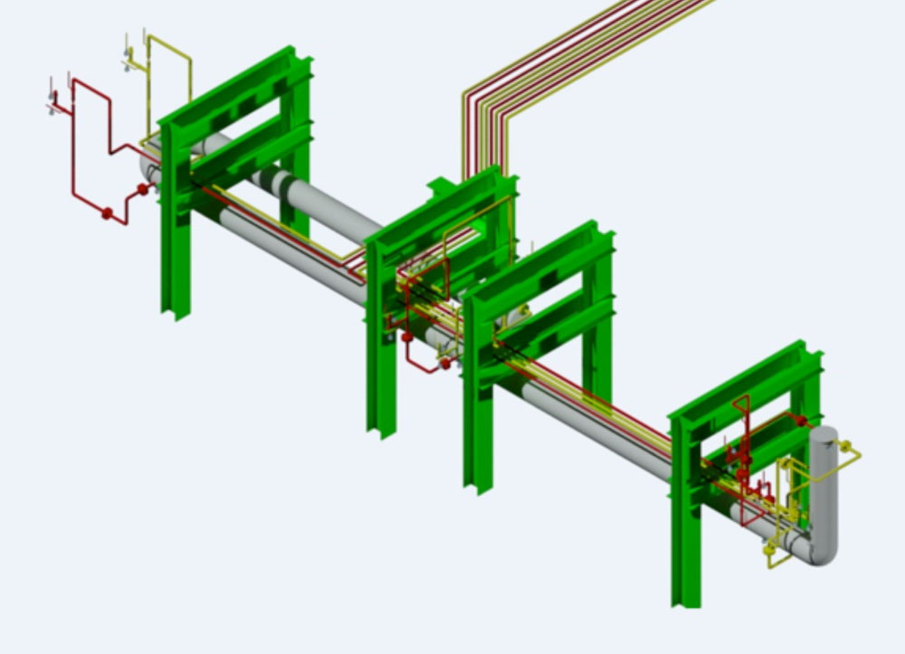
- Metering and Switching Station Modeled for the Chlorine Abatement Unit

-
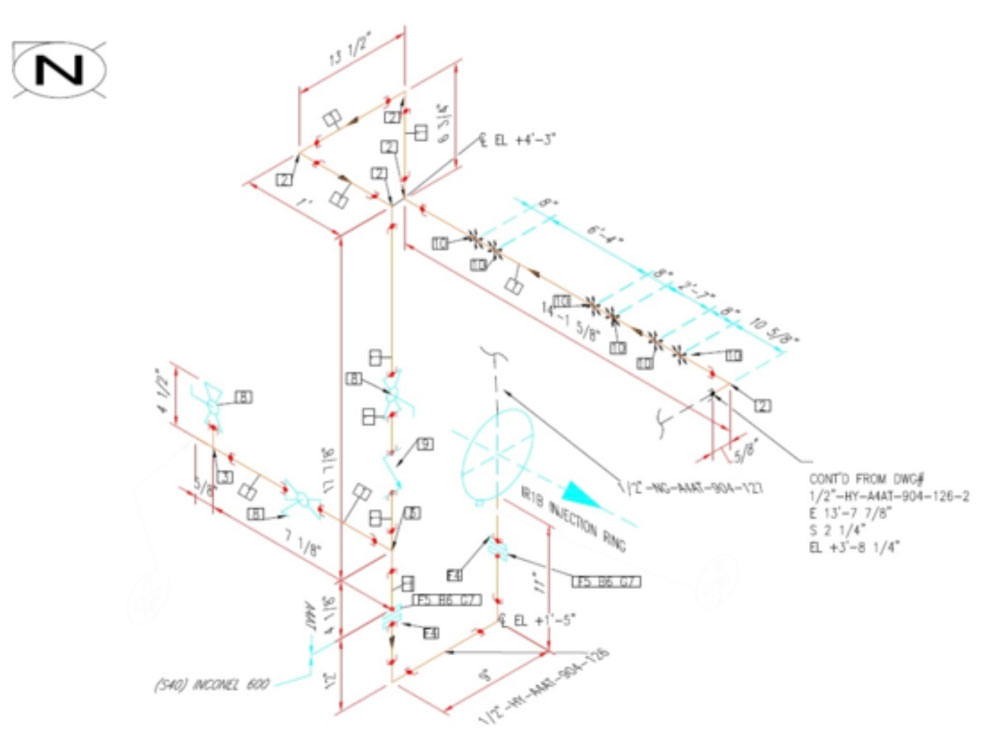
- Isometric Drawing of the ½” Hydrogen Line to the Injection Ring
-
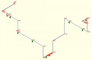
- CAESAR-II Pipe Flexibility Analysis for one of the Pipelines in the Chlorine Abatement Unit
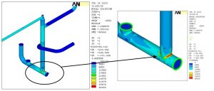
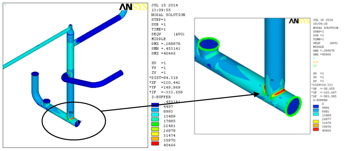
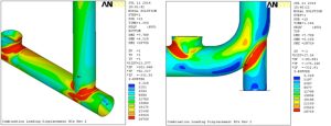
Distilling Piping Replacement – Fitness for Service Analysis
A Fitness for Service (FFS) analysis was performed to simulate the replacement of certain sections of the piping with stainless steel pipe. The following items were considered in the analysis:
- No future corrosion allowance was used for the new pipe sections; instead, 87.5% of the nominal wall thickness of the corresponding schedule of pipe was utilized to compensate for possible manufacturing tolerances.
- One pipe support was modified to model a new support style.
- All flanges in the model were checked to ensure compliance with ASME B16.5 and ASME Section VIII, Division 1 codes for flange stresses.
-
- Overall View of the Geometry
-
- Locations of Highest Von Mises Strain
-

- Location of Highest Von Mises Stresses
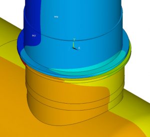
Design Calculations using ASME Section VIII Division 1 and Finite Element Analysis (FEA) for Purge Head Reactor
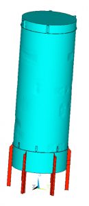
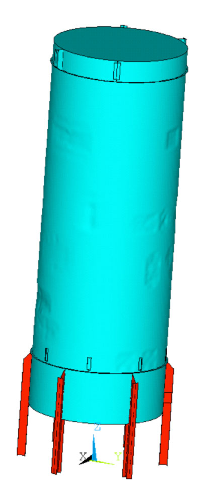
Code calculations were performed using ASME Section VIII, Division 1 to determine the code compliance of a purge head reactor with internal diameter of 85” and internal pressure of 150 psig. Local stress calculations for various attachments were also performed using WRC107. Code calculations and structural analysis were also performed on a silo sitting on the purge head by three support legs.
-
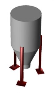
- Code calculations performed on the silo sitting on the purge head reactor

The components that were outside the scope of ASME Section VIII, Division 1, were evaluated using Finite Element Analysis (FEA). Two FEAs were performed:
- Finite Element Model (FEM) was generated to analyze clamped body flanges using (10) independent clamps. An internal pressure of 150 psig was used in the analysis of the clamps and the body flanges. This analysis was performed using brick elements.
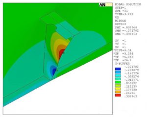
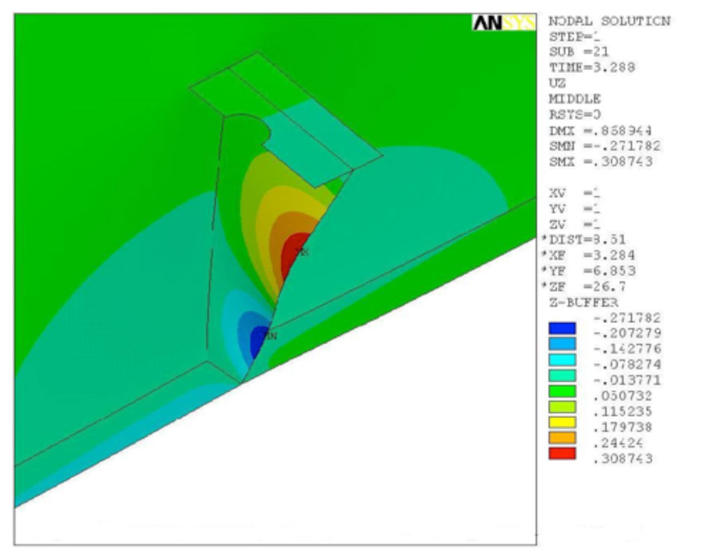
- Shell elements were used in the Finite Element Model (FEM) of the attachment between the silo and the purge head reactor. Linear and non-linear analyses were performed using the FEM.
-
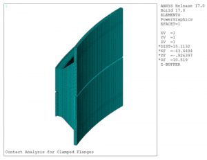
- Finite Element Mesh of Purge Head Reactor Body Flanges

-
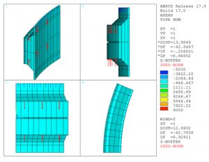
- Forces Applied to the Two Body Flanges

-
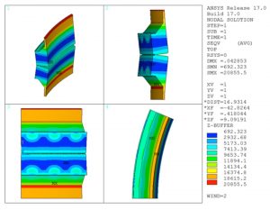
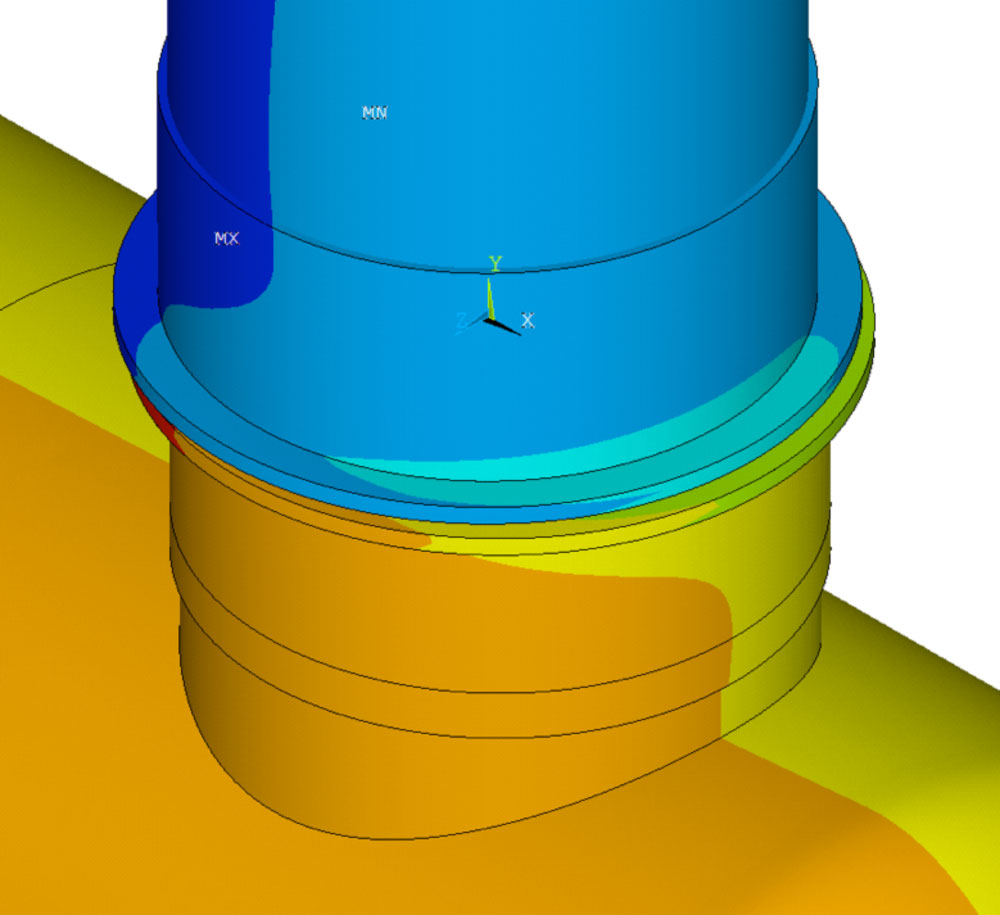
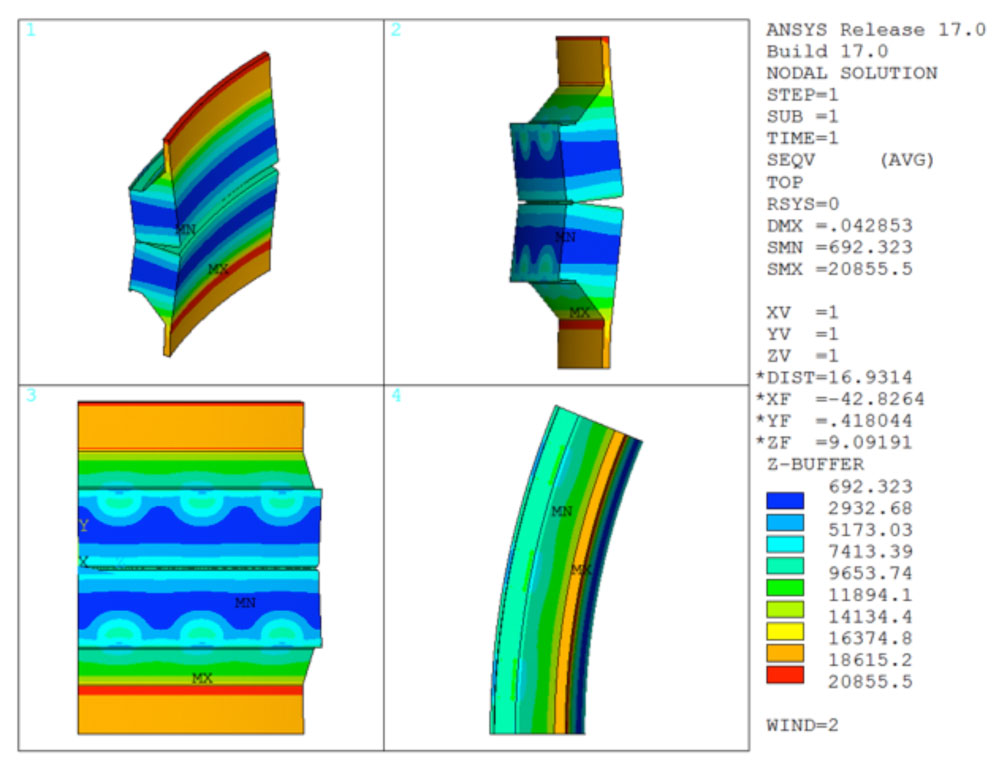
- Von Mises Stress due to Internal Pressure and Clamp Forces
-
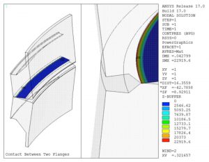
- Contact Pressure Between the Two Body Flanges Under the Internal Pressure and Clamp Forces

-
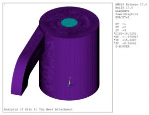
- Finite Element Model of Rectangular Attachment to the Shell of the Silo

-
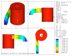
- Vertical Displacement of the Rectangular Attachment to the Shell of the Silo

-
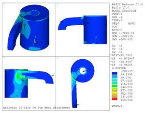
- Von Mises Stress Results for the Rectangular Attachment to the Shell of the Silo

Computational Fluid Dynamics of Two Heat Exchangers Connected in Series
Computational Fluid Dynamics (CFD) analyses of two heat exchangers in series were performed to maximize the throughput of the shell-side product. The analyses included the determination of thermal performances, pressure drops, shell-side maximum critical velocity. Baffle bypass sensitivity analysis was also performed.
-
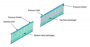
- Computational Fluid Dynamics of Two Heat Exchangers Connected in Series

-

- Side View of Computational Mesh

-
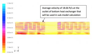
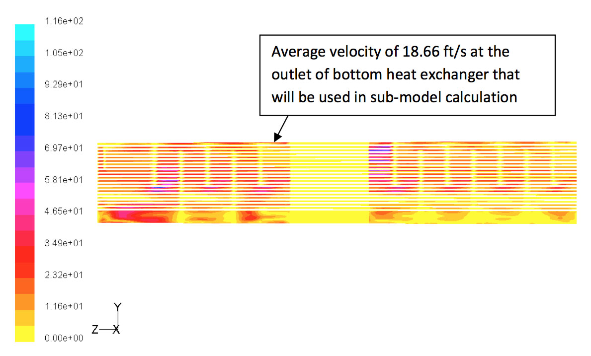
- Velocity Magnitude Contour Plot
-
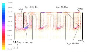
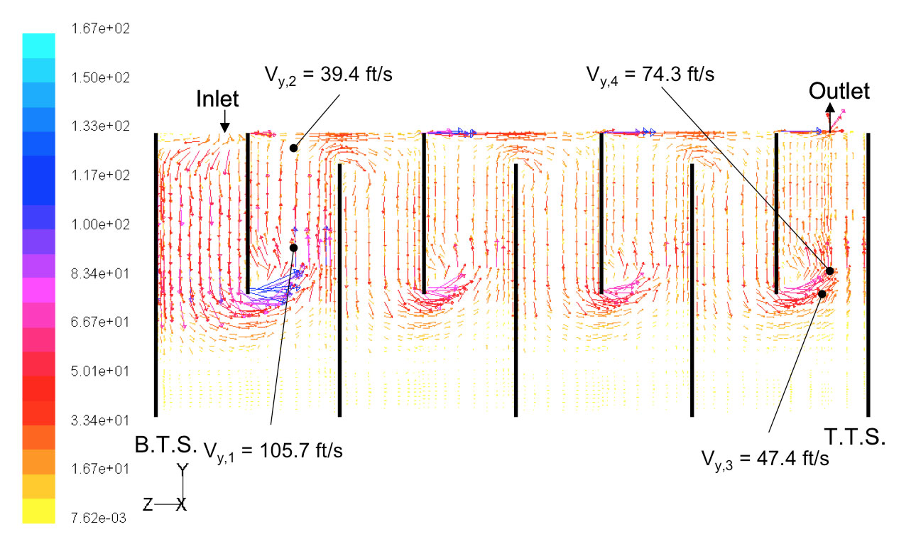
- Velocity Vector Plot at Top of the Heat Exchanger
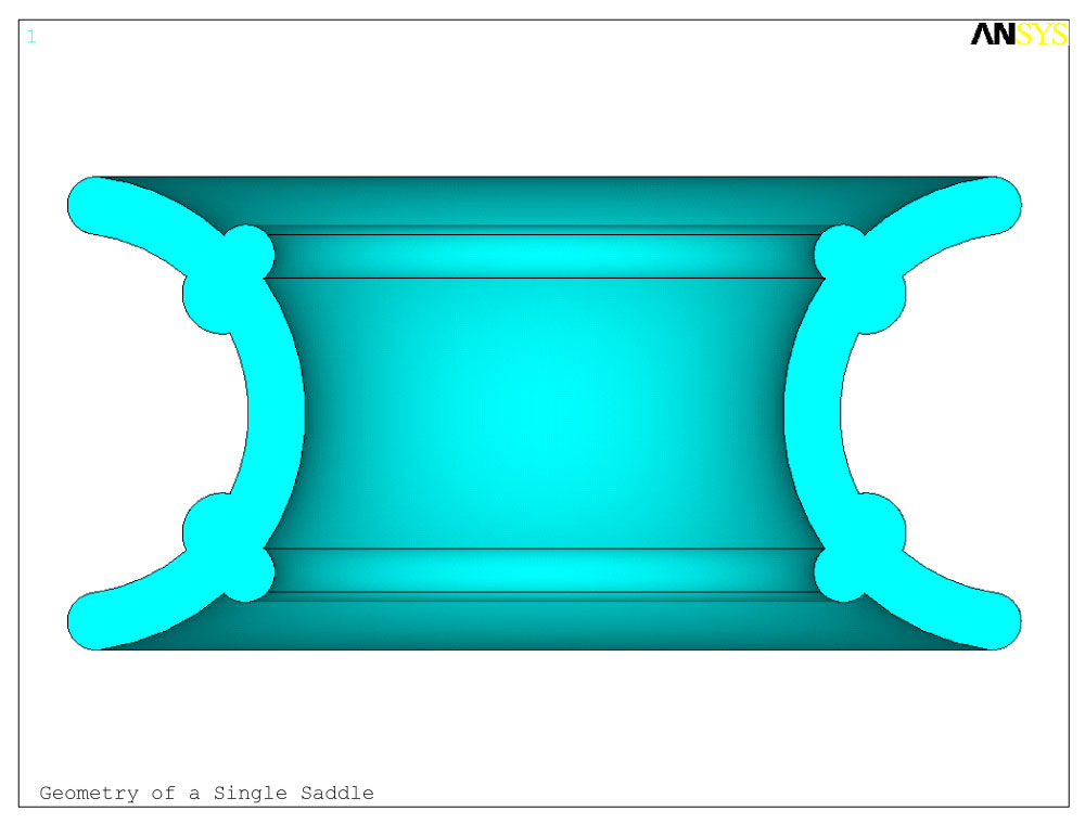
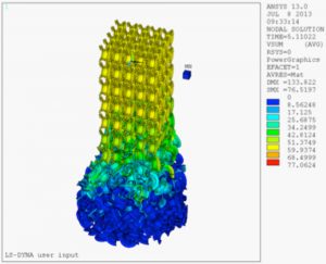
Packing Saddle Design with Computational Fluid Dynamic Analysis
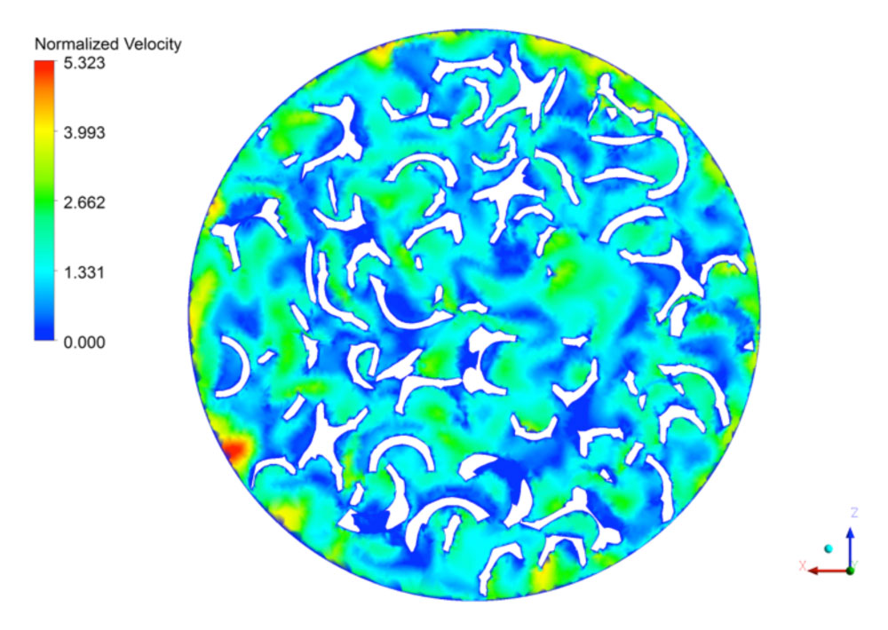
Computational Fluid Dynamics (CFD) analyses was performed to predict the effects of packing saddle shape and size on the hydraulic performance of a randomly packed column. The main metric of this analysis was pressure drop across the packed column. Results of the analysis were compared to customer supplied experimental data for validation.
-
- Geometry of the Packing Saddle
-
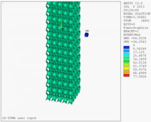
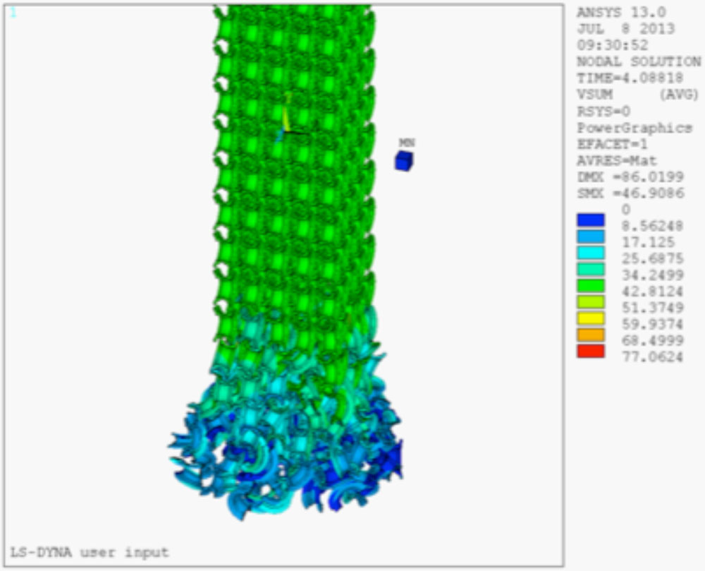
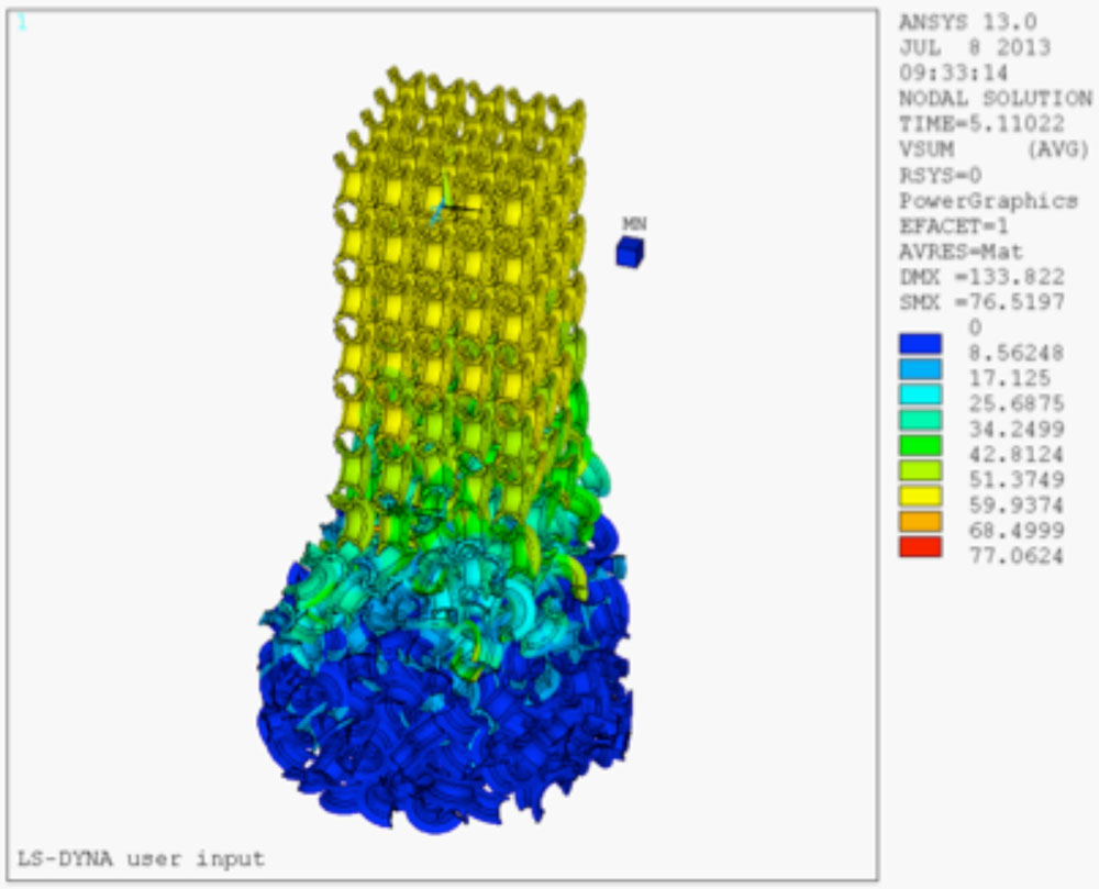
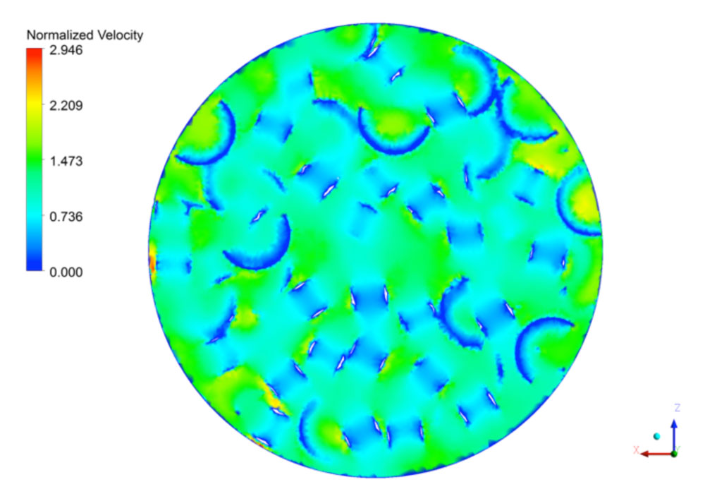
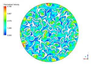
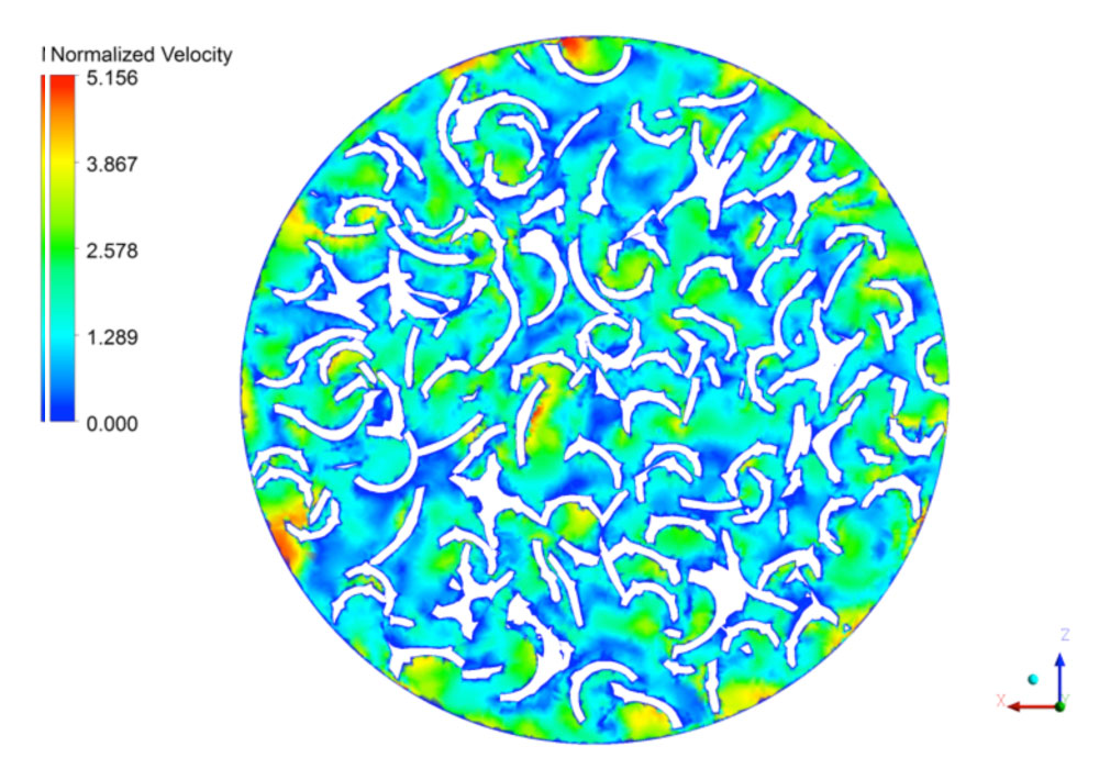
- Instantaneous Positions of Saddles at Random Points in Time (Color indicates Velocity in inches/second)

-

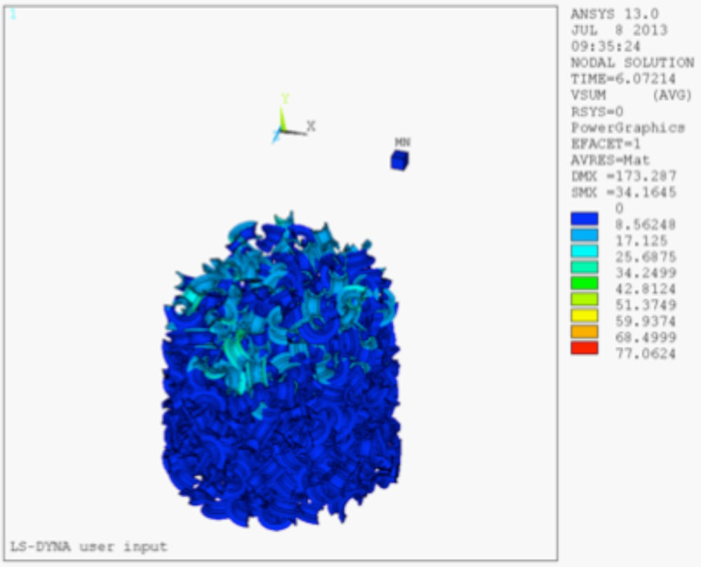
- Instantaneous Positions of Saddles at Random Points in Time (Color indicates Velocity in inches/second)
-
- Instantaneous Positions of Saddles at Random Points in Time (Color indicates Velocity in inches/second)
-

- Instantaneous Positions of Saddles at Random Points in Time (Color indicates Velocity in inches/second)
-

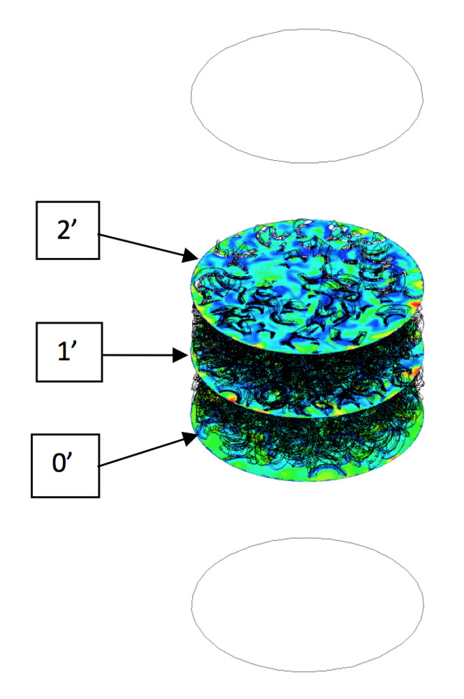
- Locations of Cross Section Planes
-
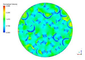
- Section 0’
-
- Section 1’
-
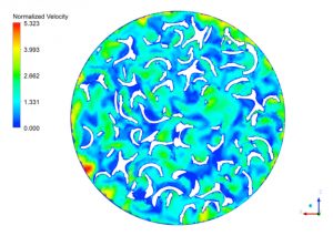
- Section 2’ Normalized Velocity Through the Various Cross Sectional Areas
Root Cause of Vibration in a Depoly Reactor
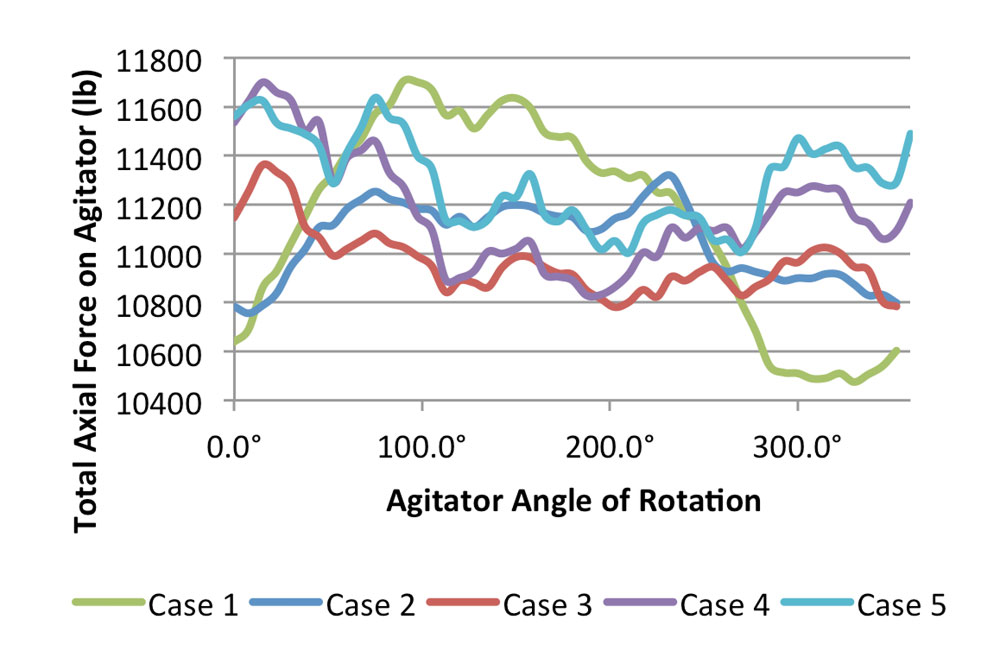
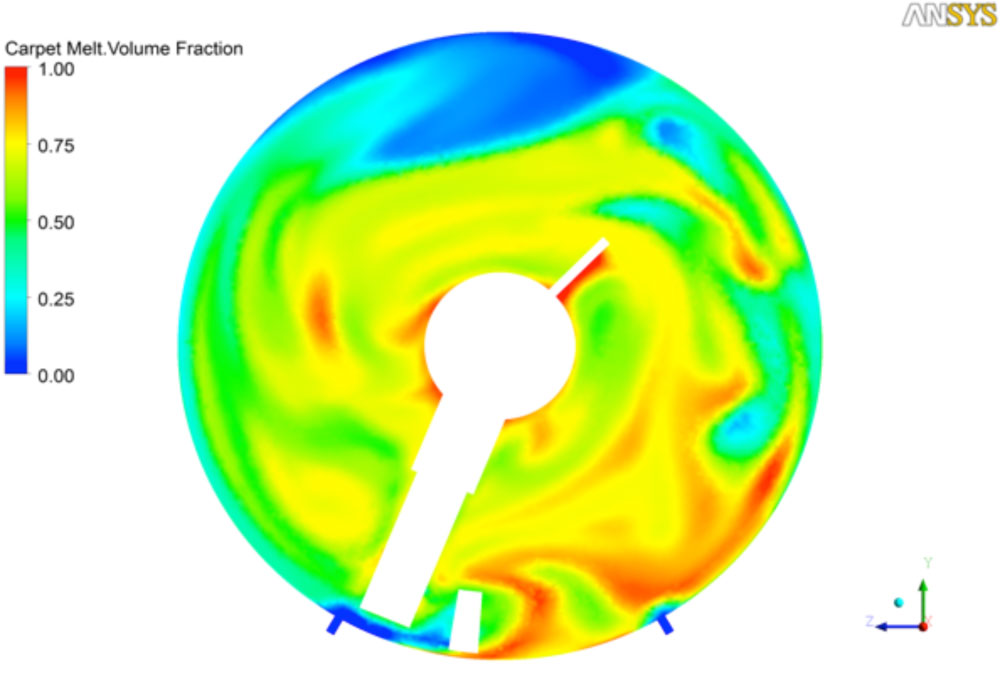
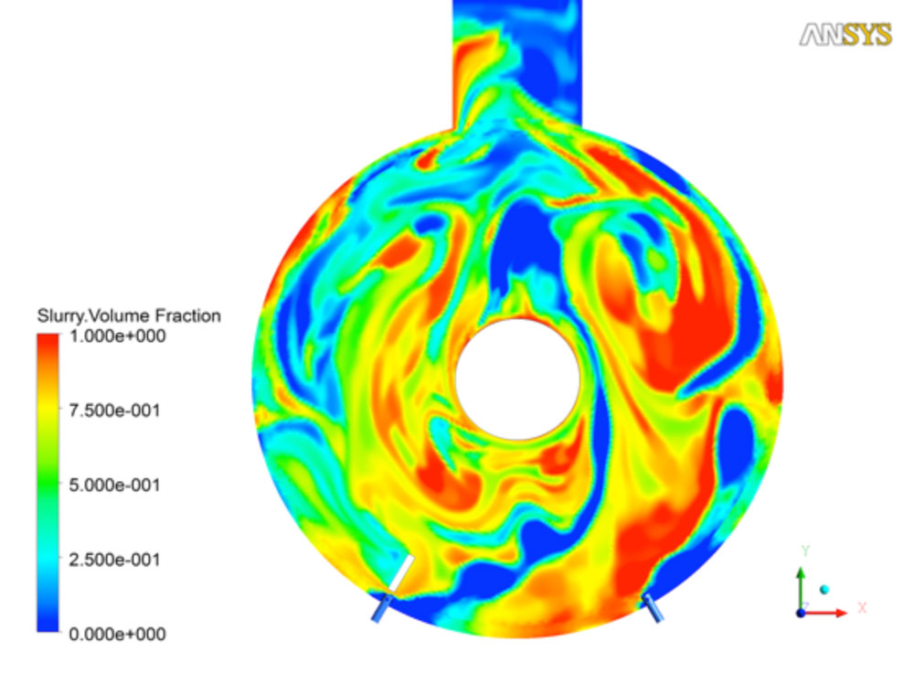
The purpose of this project was to determine the root cause of vibrations and agitator shaft packing glands failure. The vibrations of the reactor were excessive for the supporting structure. The excessive vibrations of the reactor and the agitator were observed to be the potential cause of the short life expectancy of the agitator shaft packing glands, and the structural failure of the agitator. There was a direct correlation between the vibration of the entire structure and the operating speed of the agitator. The scope of the analyses was to analyze the carpet melt dynamics within the reactor, and provide structural analyses of the reactors under the prescribed dynamic loadings. A coupled model was developed using Computational Fluid Dynamics (CFD) and Finite Element Analysis (FEA) to simulate the agitation process inside the reactors and the structural analyses of the resulting loads.
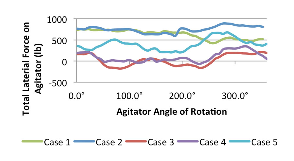
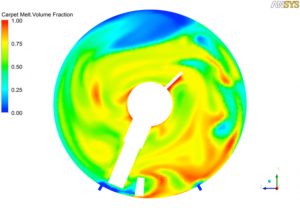
CFD was used to analyze the motion of the fluid within the reactors caused by the rotation of the agitators. To determine the effects of the changes in the melt density and viscosity on the total forces acting on the agitator surface, a small scale CFD model was created from a 20” section of the reactor. The effects of changing the wear height and the steam rate on the total forces acting on the agitator, and the degree of mixing between the steam and the melt were determined using a full scale model. The results of the CFD analyses were utilized as boundary conditions for the FEA to perform the structural analyses. Another CFD model was created to analyze the interaction of the steam and the melt in the immediate vicinity of the steam nozzles.
-
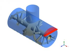
- General Layout of the Agitator

-
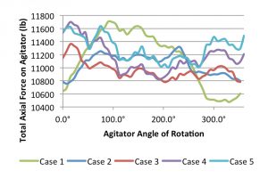
- Total Axial Force on the Agitator
-
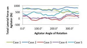
- Total Lateral Force on the Agitator
-
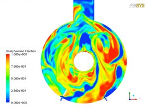
- Plot of Melt Volume Fraction
-
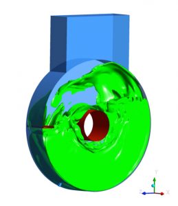
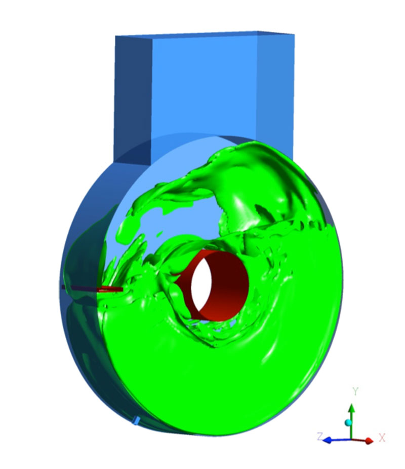
- Geometry of Small Scale Model
-
- Carpet Melt Volume Fraction in the Center of the Model
Fitness for service and Rerate Calculations of Distillation Column
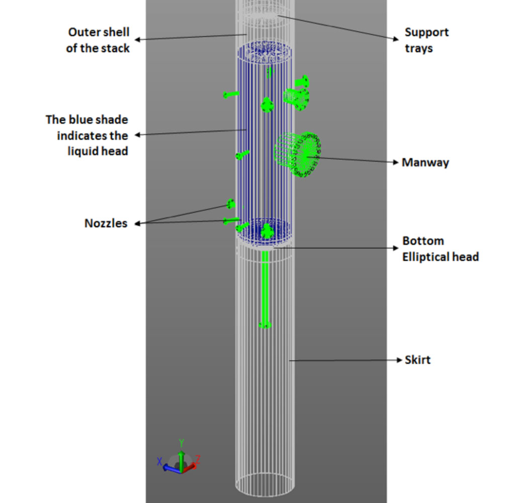
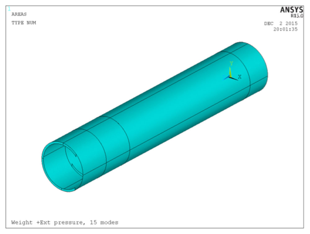
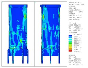
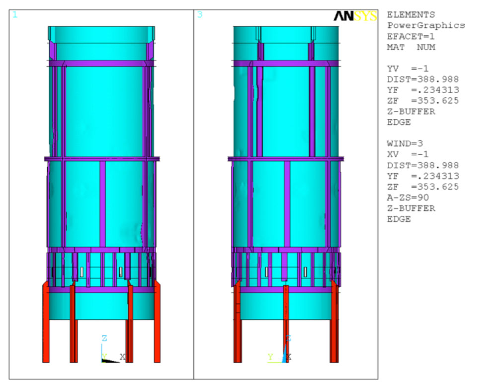
The scope of the project was to perform Fitness for Service and rerate calculations to analyze the adequacy of a distillation column. Distillation column has been in service for several years. The customer requested for additional corrosion allowance of the distillation column for several more years. Rerate of the distillation column included the shell, the heads, the skirt sections, all the nozzles with corresponding flanges, and the support trays. Calculations included the effect of wind bumpers, platform clips, and pipe supports. The structural adequacy against buckling was verified using Finite Element Analysis (FEA) for the increased corrosion allowance. The determination of structural integrity utilized both Eigen value buckling and nonlinear buckling analyses.
-
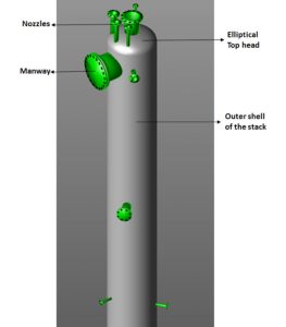
- Top of the distillation column

-

- Bottom part of the distillation column
-
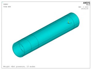
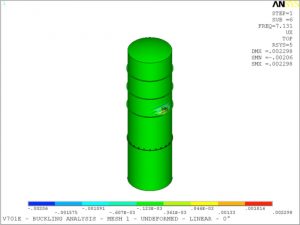
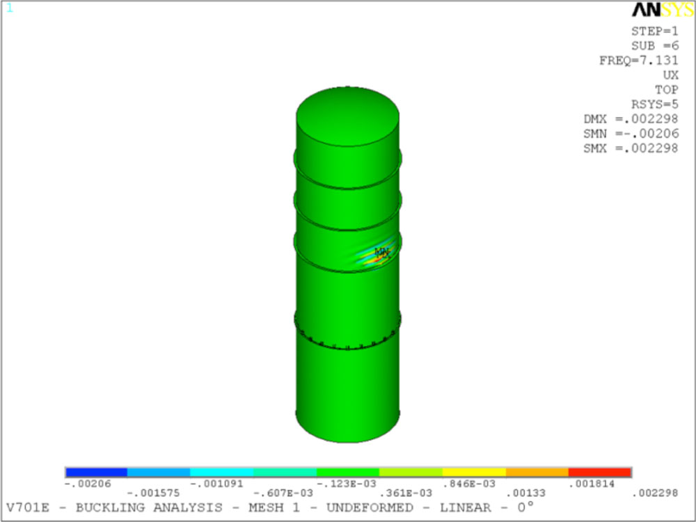
- Overview of the model used in buckling analyses
-

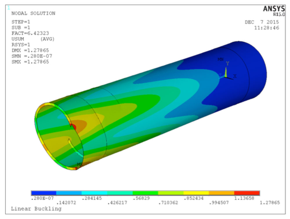
- First buckling mode: The deformation of this model was used in the nonlinear elastic-plastic analysis to determine the adequacy of tray ring supports and the tray ring support to shell weld.
-

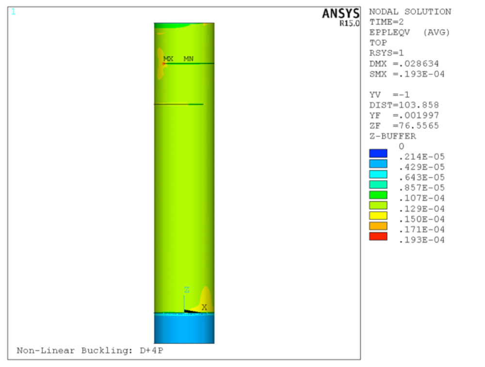
- Von-Mises plastic strain in the column
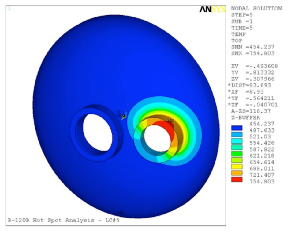
Hot Spot Analysis
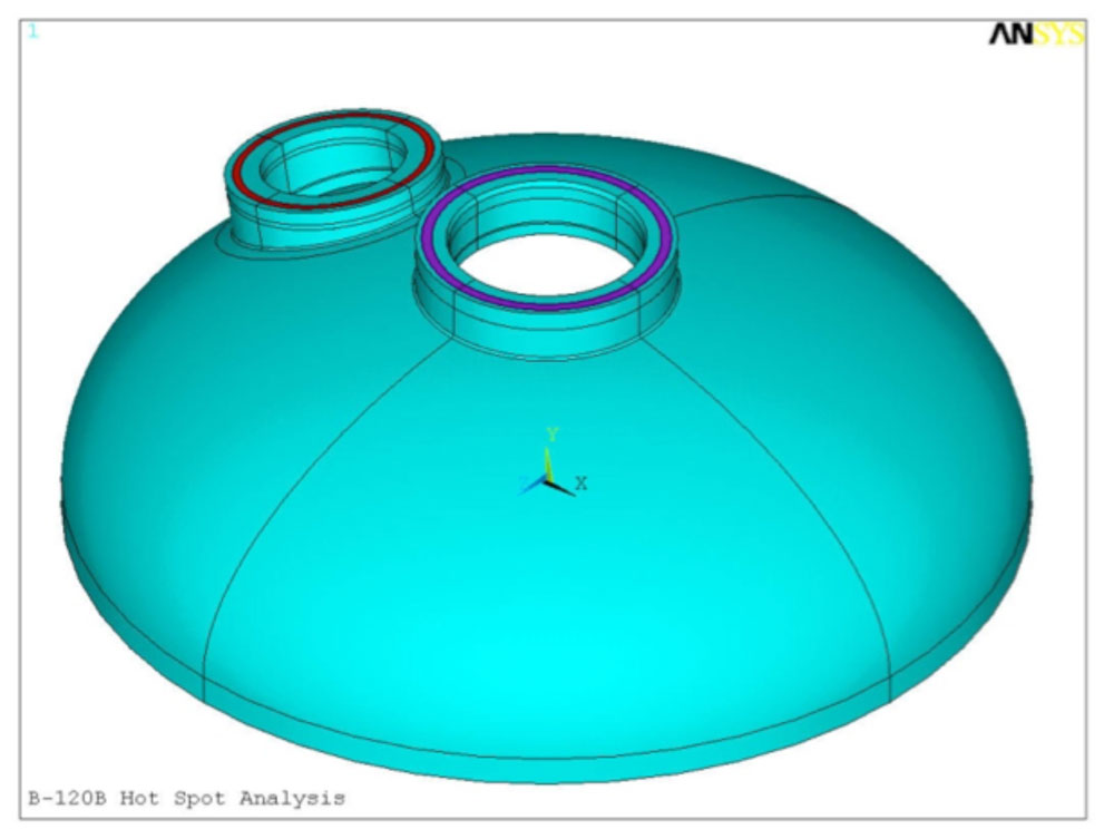
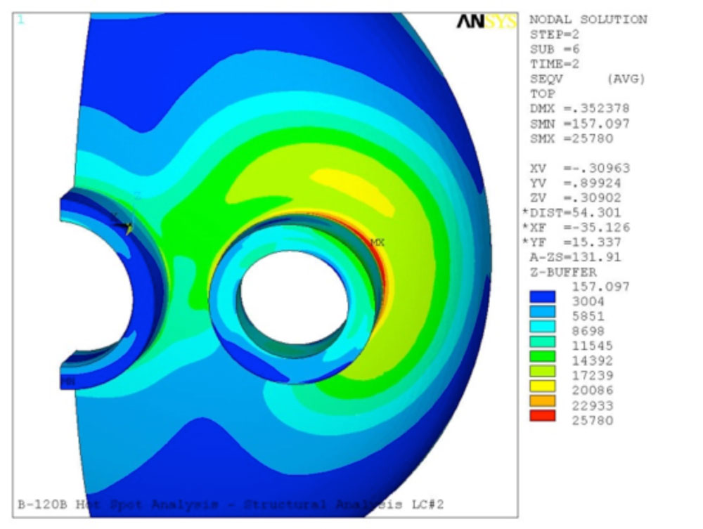
A nozzle and a portion of the vessel head were exposed to a hot spot during methane operations of a gasifier. Although there were no temperature readings at the time of the hot spot formation, the customer estimated the temperature of the hot spot region to be ~ 603°F based on the paint discoloration at the hot spot location. Thermal Finite Element Analyses (FEA) was performed in order to determine the temperature gradients between the hot spot and the rest of the model in the meridian directions, through the thickness of the head, and the corresponding nozzles. The resulting temperature profiles were used in the structural FEA to determine the formation of residual stress in the model and to verify the adequacy of the nozzles, nozzle junctions, and the head for future operation of the gasifier. The analyses were performed per API 579-1/ASME FFS-1.
The customer performed Non-Destructive Examination (NDE) to ensure there were no permanent deformations, cracks, or material deterioration at the vicinity of the hot spot.
-

- Geometry of the Head and Nozzle Penetrations
-

- Temperature Distribution Analysis on Nozzle
-
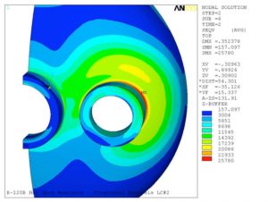
- Von Mises Stress Level on Nozzle
Distilling Piping Fitness For Service Analysis
Fitness for Service (FFS) analyses were performed on a portion of Distilling Piping utilizing Finite Element Analysis (FEA). A model of the piping system was created using shell elements. The boundary conditions obtained from Caesar II piping analysis for the remainder of the piping system were applied to the termination points of the finite element model. The structural integrity of the piping, under the operating conditions, was verified by performing FEA per API 579-1/ASME FFS-1.
-
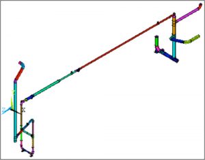
- Pipe Layout for Distillation Piping
-
- Von Mises Stress per Finite Element Analysis
-
- Von Mises Stresses per Finite Element Analysis

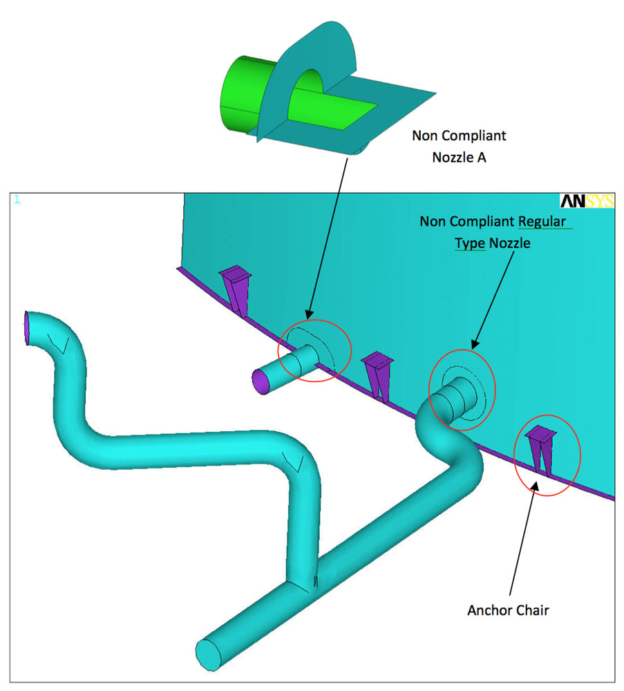
Fitness For Service of a Tank Nozzle
The customer had several tanks that did not comply with API 650. A Fitness for Service (FFS) was performed using Finite Element Analysis with the load combinations mandated by API 579-1/ASME FFS-1, Table B1.2. The FFS included the linear and limit load analyses for the nozzles. Non-linear buckling analysis was performed to determine the adequacy of the anchor chair gusset plates under wind/seismic forces.
-

- Tank with Nozzle Layout
-

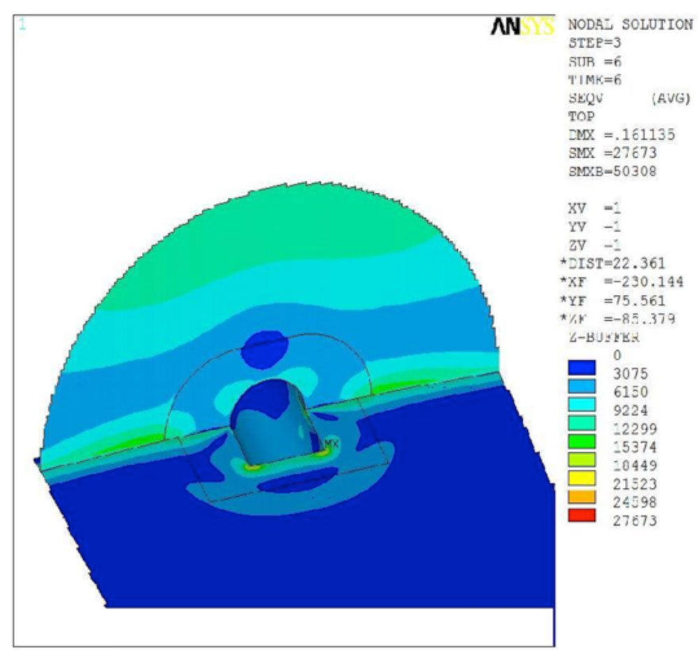
- Linear Analysis: von Mises Stress around Nozzle A
-
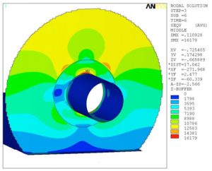
- Linear Analysis: von Mises Stress around Regular Type Nozzle

-
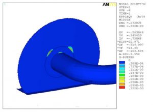
- Limit Load Analysis: Von Mises Plastic Strain around Regular Type Nozzle

-
- Non Linear Anchor Chair Gusset Buckling Analysis
Fitness for Service/Repair for Vertical Heater
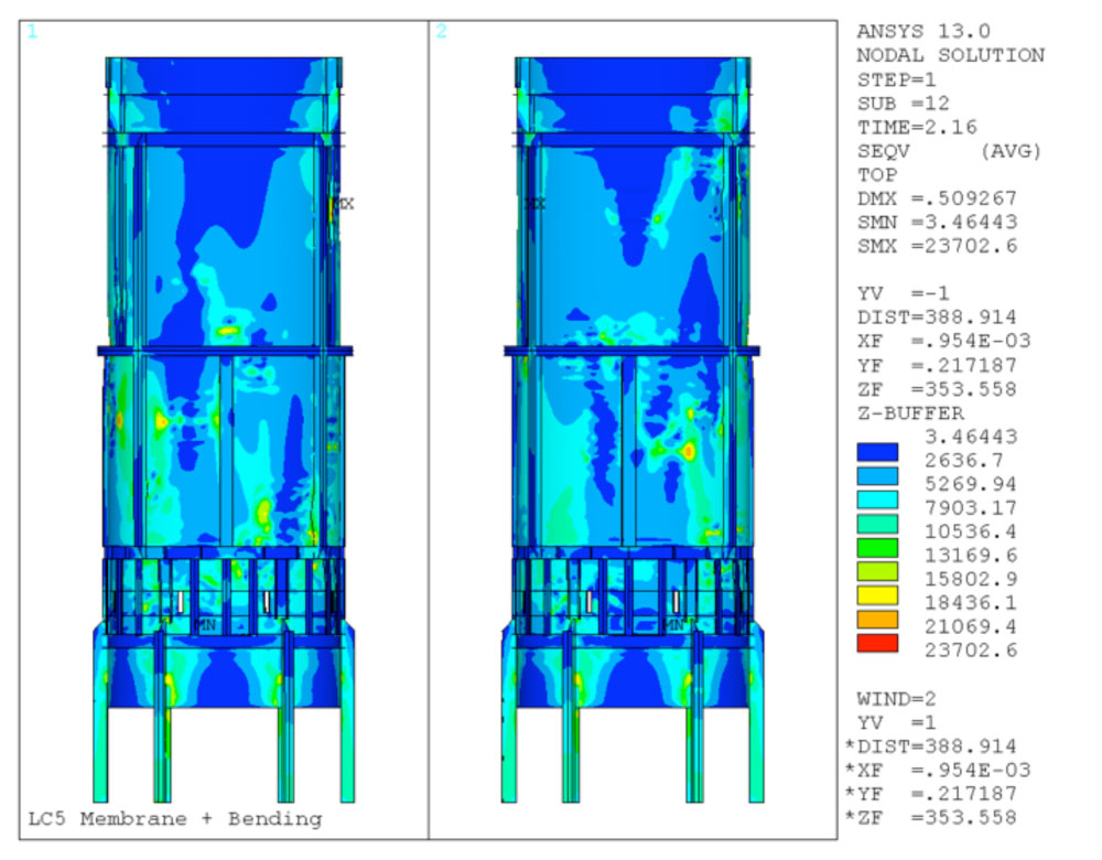
The scope of the analysis was to perform Fitness For Service (FFS) analyses and to provide a repair plan for a vertical heater. The heater shell had reduced thicknesses and severe deformation along the longitudinal and the circumferential directions (dents, gouges, and misalignments). The analyses were to consider the deformed geometry and the reduced shell thicknesses. The analyses utilized the loading prescribed by the customer, including the increased weight due to modification of the convection section. Modifications to the convection box section and the stack positioned on the top of the heater resulted in an increased weight of the convection section.
Fitness For Service analyses were performed to study the structural integrity of the heater for the current condition per API 579-1. Based on the results of these analyses, structural members were added to the model, and the new design was analyzed by performing Fitness For Service analyses under the operating conditions, including the exposure of the heater to the wind loading from several directions. Thermal analyses were performed for various conditions to verify the structural integrity of the new design. Due to the time constraint, the customer was unable to complete the attachment weld of all the structural members to the shell before the repairs to the vertical radiant coils were completed. Therefore, the minimum required weld length for the structural members was determined considering a maximum wind speed of 45 MPH.
-
- Geometry of the Initial State of the Heater as Measured by the Customer
-
- Membrane + Bending Stress for LC 1 – South View and North View

-

- New Design with Reinforcing Structural Members
-
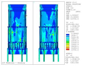
- Membrane + Bending Stress for the New Design – South View and North View
Thermal Stress Analysis of a Blowdown Header
One of our customers experienced extensive cracking in their blowdown header of their hydrocarbon blowdown system. The blowdown header was fabricated from 36” Schedule 40 pipe. The thickness of the blowdown header varied between 3/8” to 3/4” thick along the length.
-
- General Layout of the Coke Drums and the Associated Blowdown System
-
- Section of the Blowdown Header Where Most of the Crack-Like-Flaws Were Observed
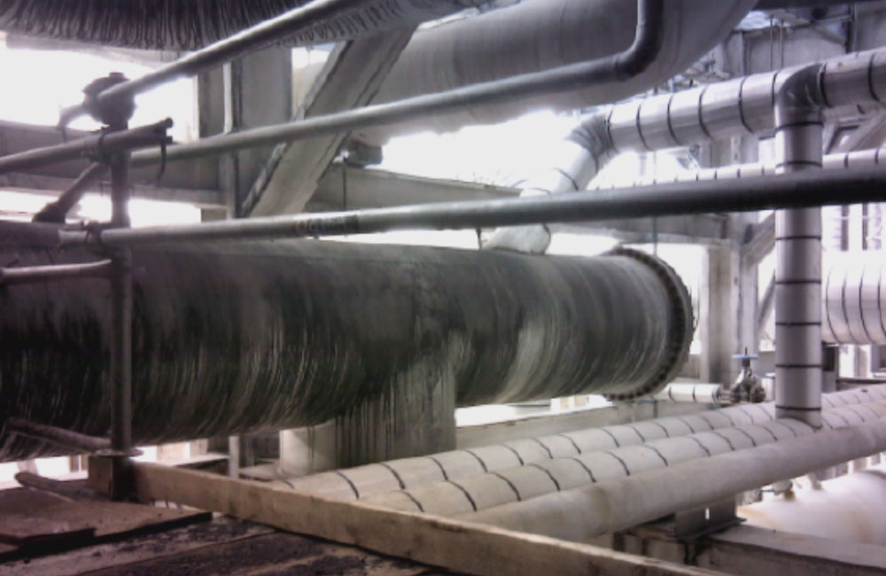
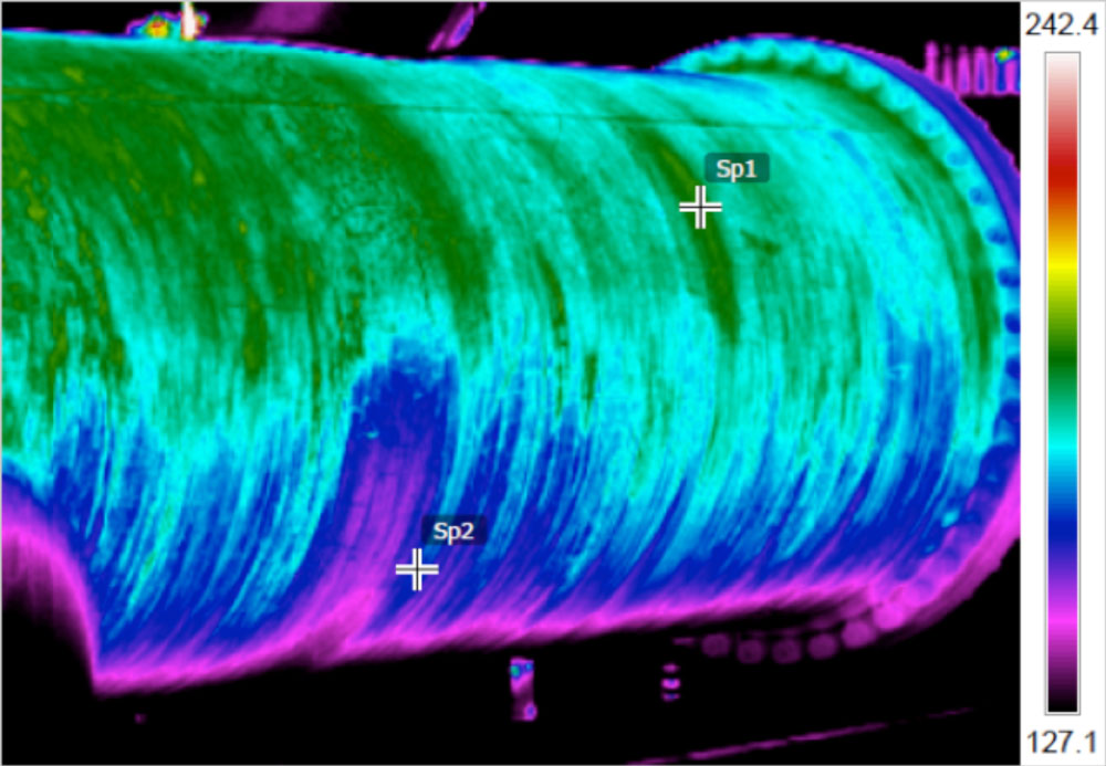
IR thermal images of the blowdown header were taken during operation to assess the temperature distribution in the piping. Thermocouples were also installed to record the temperature of the blowdown header at different locations. Based on the thermal images and thermocouple readings, it was determined that a significant temperature gradient was present in the circumferential direction of the header at various stages of the operating cycle.
-
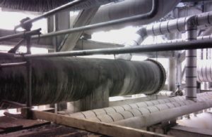
- Photograph of Blowdown Header
-

- IR Thermal Image of Blowdown Header
The crack-like-flaws were circumferential and approximately straddled the centerline of the header (6 o’clock position). The crack-like-flaws seemed to initiate from the inside surface of the header propagating radially outward.
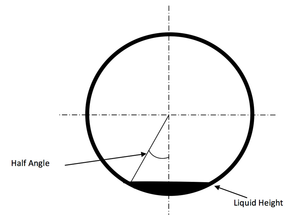
The crack-like-flaws were observed during routine inspection. Two holes were drilled through the header at the ends of the crack to arrest future crack propagation. This was done in preparation for clamp installation. When the holes were drilled, a significant amount of liquid hydrocarbon drained from the header. This indicated that a pool of residual liquid hydrocarbon remained in the pipe, and had not properly drained from this location. This residual liquid was determined to have a significant effect on the life expectancy of the blowdown header.
-
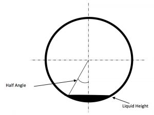
- Representation of the Liquid Hydrocarbon Pooling in the Blowdown Header
-

- Blowdown Header Internal Layout

The blowdown system was analyzed using Computational Fluid Dynamics (CFD), Finite Element Analysis (FEA), and pipe stress analysis. The boundary conditions used for the analyses were provided by the customer for a typical operating cycle. An operating cycle was defined as each of the four Coke drums filling, quenching, draining, and drilling.
*NOTE: Insert animation here for the cycle described above (File “Transient 3 Cycle Oblique”)*
The circumferential thermal gradient caused a differential longitudinal growth between the upper and lower regions of the header. This caused the longitudinal membrane stress of the upper region to be in compression, while the lower region was in tension. Due to the relative size of the lower region compared to the upper region, the stress level in the lower region was significantly greater than the upper region. In addition, the thermal gradient caused ovalling of the header. The ovality of the header was observed to be maximum at locations with relative greater stiffness, such as nozzle to header junctions. The ovality was intensified at the thicker transitions due to the large change in stiffness between the 3/4” and 3/8” thick sections.
-
- Ovalling-Blowdown-Header-Due-Thermal-Stresses

Additionally, fatigue analysis calculations were performed for the locations with lowest and greatest life expectancies. Fatigue analysis was also performed for the sections of the blowdown header at locations with locations with hydrocarbon liquid accumulations. The calculations were performed for a welding residual stress of 48 ksi since no Post Weld Heat Treatment (PWHT) was performed. It was determined that the weld quality had a significant impact on the life expectancy of the blowdown header welds. Fatigue calculations were performed in accordance with the latest ASME Section VIII, Division 2, Part 5.5.5.
The following analyses were performed:
- Calculation of thermal boundary conditions (analytical method)
- Calculation of thermal boundary conditions (CFD)
- Intended normal operating condition for original design
- Effect of circumferential thermal gradient on life expectancy
- Calculation of liquid level in blowdown header (includes evaporation)
- Effect of liquid level on circumferential thermal gradient
- Effect of insulating the blowdown header on life expectancy
- Effect of thickness transitions on life expectancy
- Potential long-term repair for blowdown header
Thermal stress analyses of the blowdown header were performed using ANSYS® Finite Element Analysis (FEA) software. A Three-Dimensional (3-D) Finite Element Model (FEM) was developed to perform the analyses. All parts of the hydrocarbon blowdown system were included in the FEM. The element type used for each major component in the model is described below. The element types are provided for both the thermal and structural analyses that were performed.
- Piping, vessels, supports (other than spring and hanger type supports)
- Structural – SHELL181, 4-node, 3-D solid element with six degrees of freedom per node: translations and rotations in x, y, and z directions.
- Thermal – SHELL57, 4-node, 3-D solid thermal conduction element with one degree of freedom per node: temperature.
Shell Distortion/Buckling – Fitness for Service Assessment
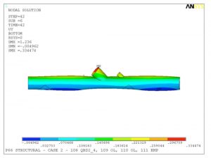
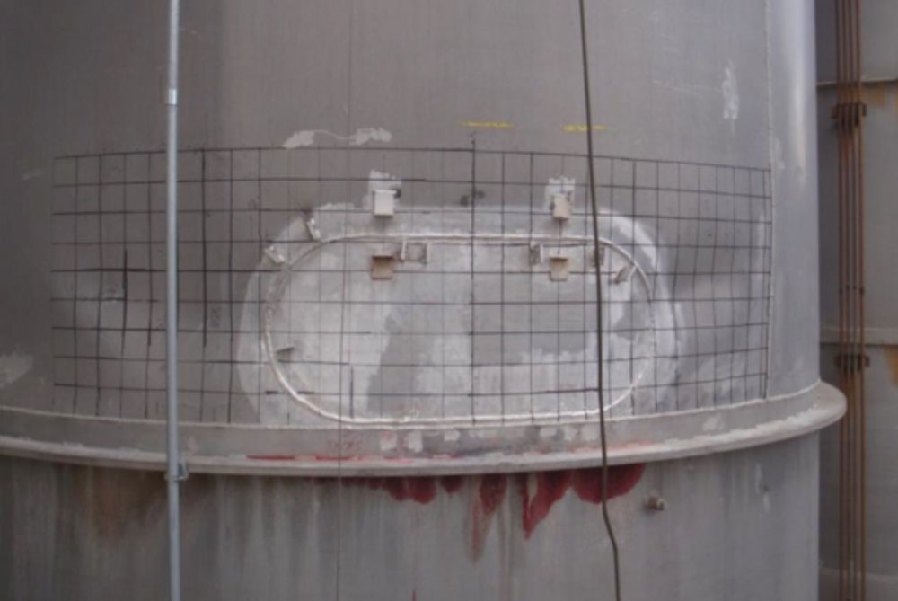
To remove a crack-like flaw near the base of a silo shell, the customer replaced the region surrounding the crack with a flush patch. However, due to the local heat produced during welding, the silo shell in the general region of the flush patch became distorted upon cooling to ambient temperature. Therefore, a Fitness for Service (FFS) assessment was performed to determine if the silo was adequate for continued service under design loads with the distorted geometry of the shell.
The silo was analyzed using elastic-plastic Finite Element Analysis (FEA) per API 579-1/ASME FFS-1 code. The model included the deformed shape of the shell as defined by measurements provided by the customer. Based on the shell distortion and the design loads for the silo, the primary mode of failure considered for this analysis was buckling.
-
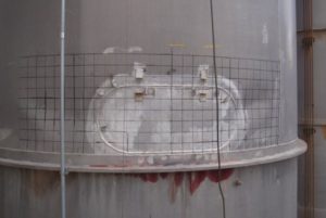
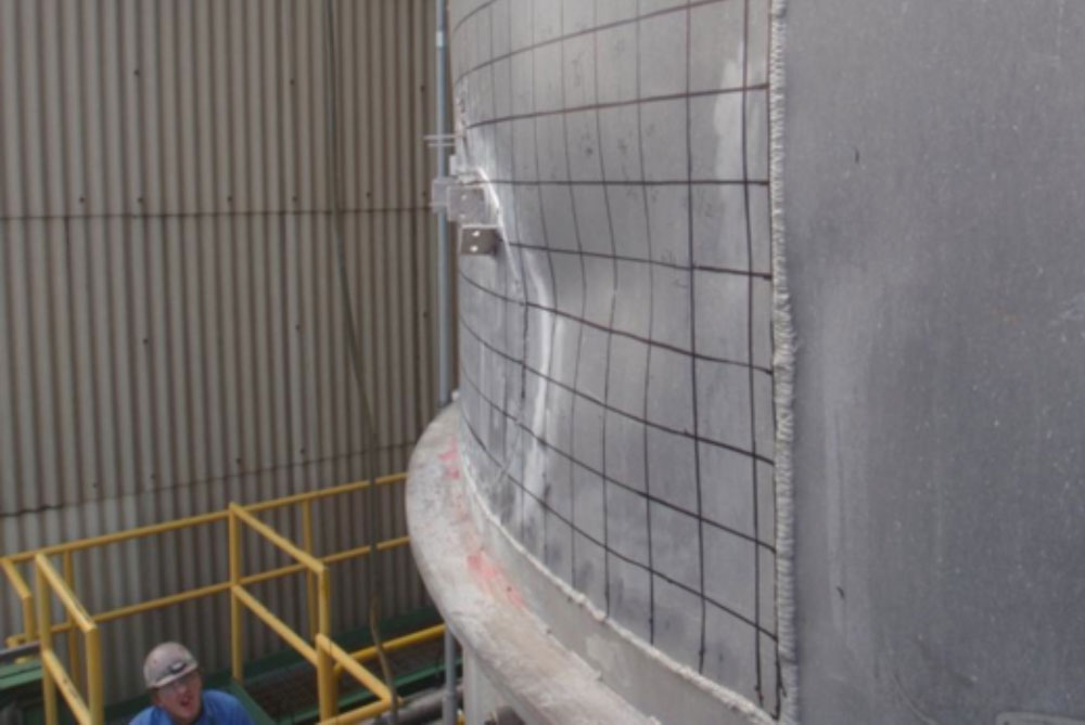
- Photographs of the Actual Shell Distortion
-
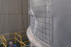
- Photographs of the Actual Shell Distortion
-
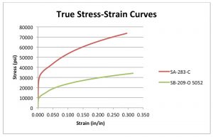
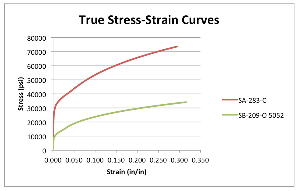
- True Stress-Strain Curves for the Materials
-
- First Local Buckling Mode Shape for Shell
-
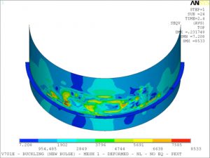
- von Mises Stress Profile in Buckling Section
