Fatigue and Plastic Collapse Analysis on Waste Heat Boiler
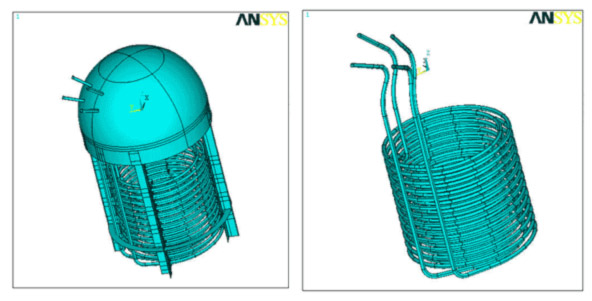
The scope of this project was to perform fatigue and plastic collapse analyses on a waste heat boiler that was used to cool raw syngas from the outlet of the gasifier. The thermal energy of the gas is used to produce High Pressure (HP) saturated steam on the shell side of the waste heat boiler.
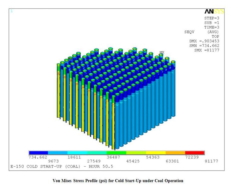
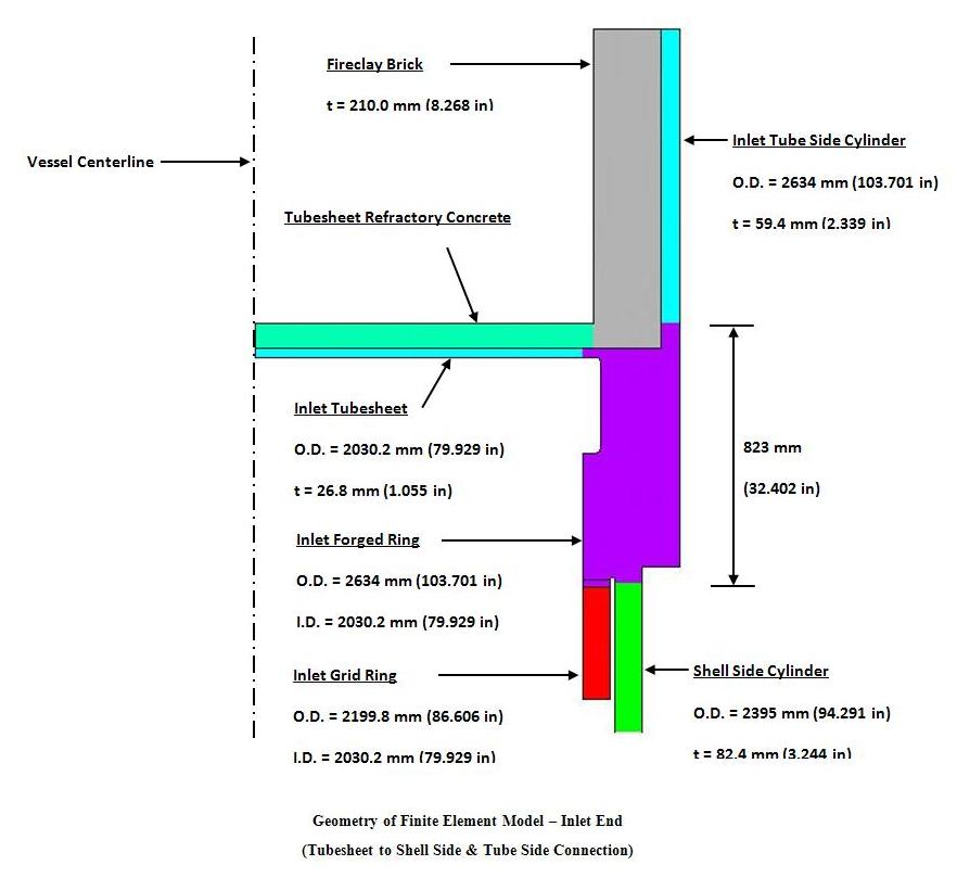
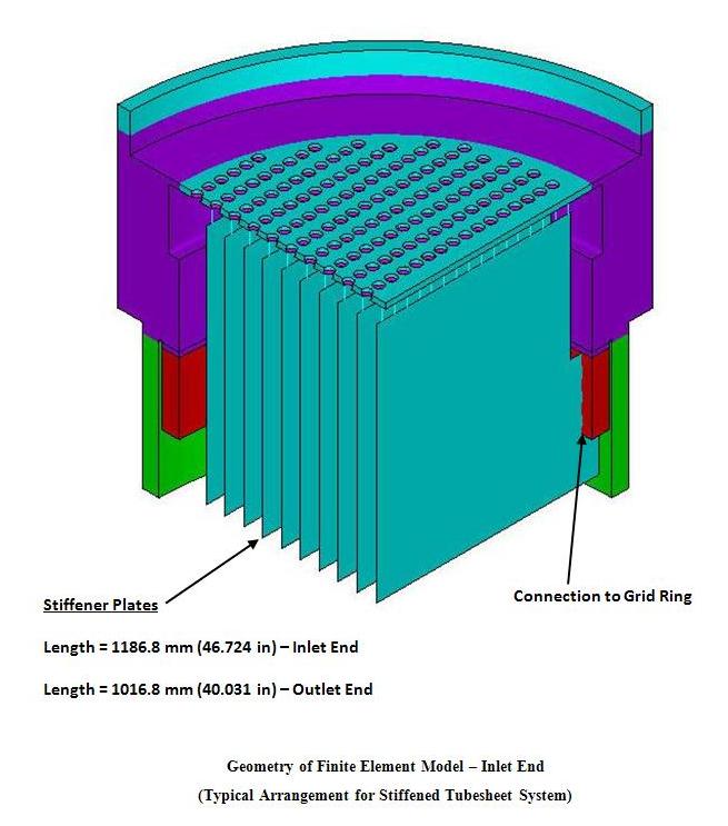
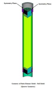
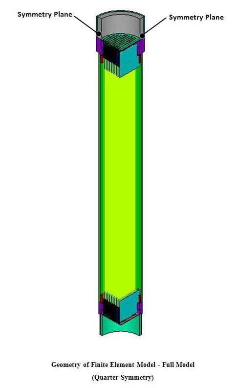
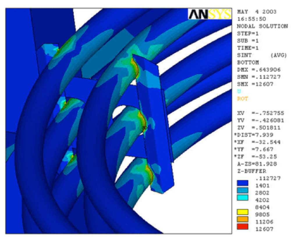
Fatigue Analysis: A Three-Dimensional (3D) Finite Element Model was developed to perform Finite Element Analysis (FEA) for the boiler. Fatigue analysis was performed to determine the permissible number of cycles remaining for the tubes which were to be salvaged.
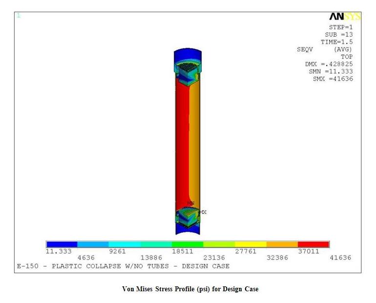
Plastic Collapse Analysis: This analysis was a supplement for salvaging the boiler tubes. The analysis was performed to determine the safety of the waste heat boiler in the event that a tube, or tubes, would fail.
-

- Stresses2
-

- Stresses1
-
- Geometry3
-

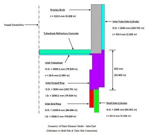
- Geometry2
-
- Geometry1
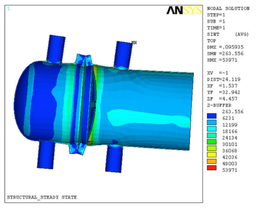
Thermal Stress Analysis of a Blowdown Header
One of our customers experienced extensive cracking in their blowdown header of their hydrocarbon blowdown system. The blowdown header was fabricated from 36” Schedule 40 pipe. The thickness of the blowdown header varied between 3/8” to 3/4” thick along the length.
-
- General Layout of the Coke Drums and the Associated Blowdown System
-
- Section of the Blowdown Header Where Most of the Crack-Like-Flaws Were Observed
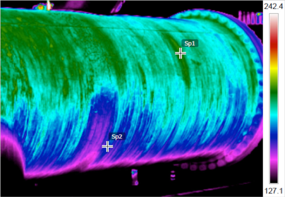
IR thermal images of the blowdown header were taken during operation to assess the temperature distribution in the piping. Thermocouples were also installed to record the temperature of the blowdown header at different locations. Based on the thermal images and thermocouple readings, it was determined that a significant temperature gradient was present in the circumferential direction of the header at various stages of the operating cycle.
-
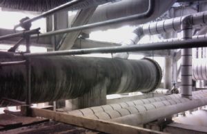
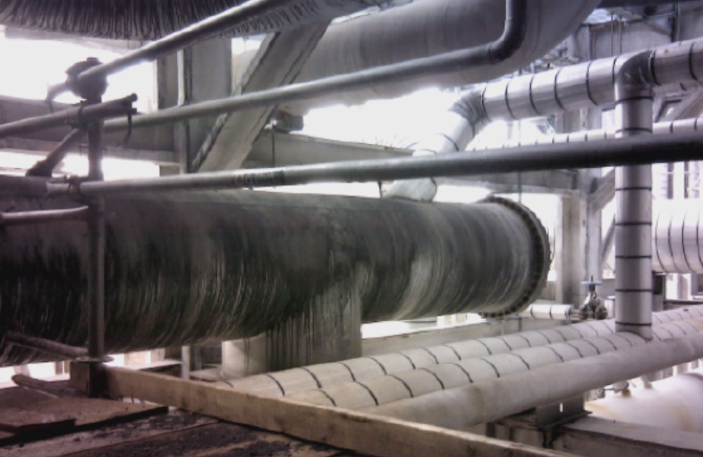
- Photograph of Blowdown Header
-

- IR Thermal Image of Blowdown Header
The crack-like-flaws were circumferential and approximately straddled the centerline of the header (6 o’clock position). The crack-like-flaws seemed to initiate from the inside surface of the header propagating radially outward.
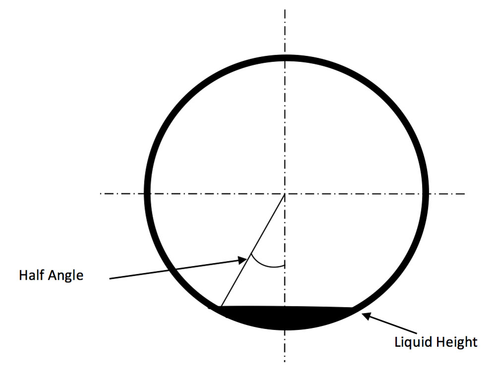
The crack-like-flaws were observed during routine inspection. Two holes were drilled through the header at the ends of the crack to arrest future crack propagation. This was done in preparation for clamp installation. When the holes were drilled, a significant amount of liquid hydrocarbon drained from the header. This indicated that a pool of residual liquid hydrocarbon remained in the pipe, and had not properly drained from this location. This residual liquid was determined to have a significant effect on the life expectancy of the blowdown header.
-
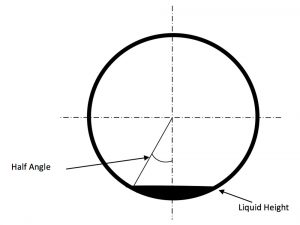
- Representation of the Liquid Hydrocarbon Pooling in the Blowdown Header
-

- Blowdown Header Internal Layout

The blowdown system was analyzed using Computational Fluid Dynamics (CFD), Finite Element Analysis (FEA), and pipe stress analysis. The boundary conditions used for the analyses were provided by the customer for a typical operating cycle. An operating cycle was defined as each of the four Coke drums filling, quenching, draining, and drilling.
*NOTE: Insert animation here for the cycle described above (File “Transient 3 Cycle Oblique”)*
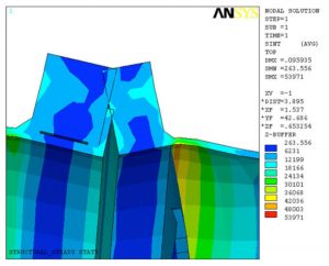
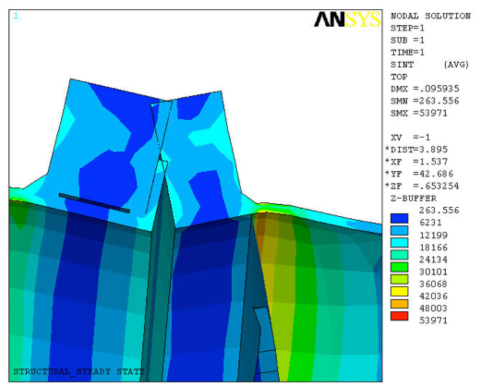
The circumferential thermal gradient caused a differential longitudinal growth between the upper and lower regions of the header. This caused the longitudinal membrane stress of the upper region to be in compression, while the lower region was in tension. Due to the relative size of the lower region compared to the upper region, the stress level in the lower region was significantly greater than the upper region. In addition, the thermal gradient caused ovalling of the header. The ovality of the header was observed to be maximum at locations with relative greater stiffness, such as nozzle to header junctions. The ovality was intensified at the thicker transitions due to the large change in stiffness between the 3/4” and 3/8” thick sections.
-
- Ovalling-Blowdown-Header-Due-Thermal-Stresses

Additionally, fatigue analysis calculations were performed for the locations with lowest and greatest life expectancies. Fatigue analysis was also performed for the sections of the blowdown header at locations with locations with hydrocarbon liquid accumulations. The calculations were performed for a welding residual stress of 48 ksi since no Post Weld Heat Treatment (PWHT) was performed. It was determined that the weld quality had a significant impact on the life expectancy of the blowdown header welds. Fatigue calculations were performed in accordance with the latest ASME Section VIII, Division 2, Part 5.5.5.
The following analyses were performed:
- Calculation of thermal boundary conditions (analytical method)
- Calculation of thermal boundary conditions (CFD)
- Intended normal operating condition for original design
- Effect of circumferential thermal gradient on life expectancy
- Calculation of liquid level in blowdown header (includes evaporation)
- Effect of liquid level on circumferential thermal gradient
- Effect of insulating the blowdown header on life expectancy
- Effect of thickness transitions on life expectancy
- Potential long-term repair for blowdown header
Thermal stress analyses of the blowdown header were performed using ANSYS® Finite Element Analysis (FEA) software. A Three-Dimensional (3-D) Finite Element Model (FEM) was developed to perform the analyses. All parts of the hydrocarbon blowdown system were included in the FEM. The element type used for each major component in the model is described below. The element types are provided for both the thermal and structural analyses that were performed.
- Piping, vessels, supports (other than spring and hanger type supports)
- Structural – SHELL181, 4-node, 3-D solid element with six degrees of freedom per node: translations and rotations in x, y, and z directions.
- Thermal – SHELL57, 4-node, 3-D solid thermal conduction element with one degree of freedom per node: temperature.
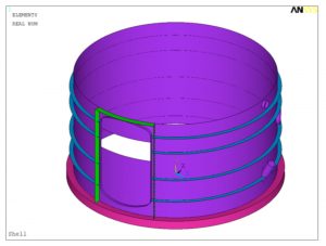
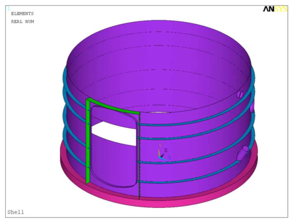
Shell Distortion/Buckling – Fitness for Service Assessment
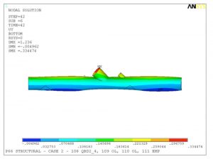
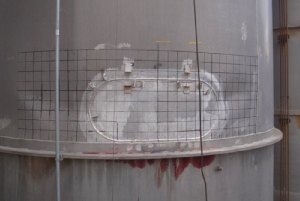
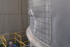
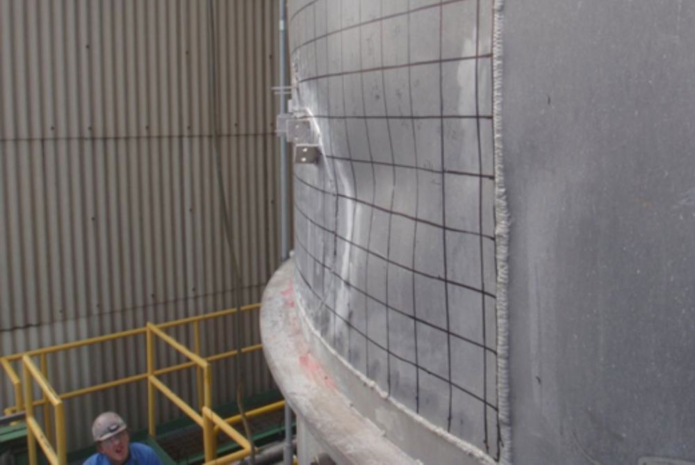
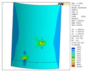
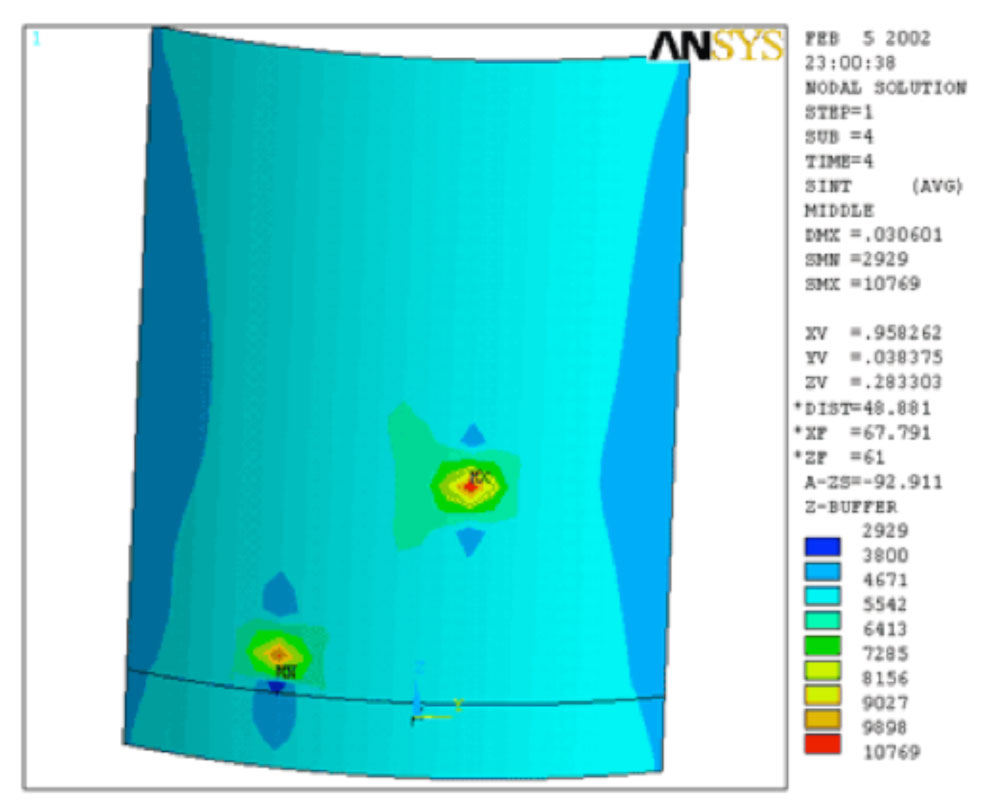
To remove a crack-like flaw near the base of a silo shell, the customer replaced the region surrounding the crack with a flush patch. However, due to the local heat produced during welding, the silo shell in the general region of the flush patch became distorted upon cooling to ambient temperature. Therefore, a Fitness for Service (FFS) assessment was performed to determine if the silo was adequate for continued service under design loads with the distorted geometry of the shell.
The silo was analyzed using elastic-plastic Finite Element Analysis (FEA) per API 579-1/ASME FFS-1 code. The model included the deformed shape of the shell as defined by measurements provided by the customer. Based on the shell distortion and the design loads for the silo, the primary mode of failure considered for this analysis was buckling.
-
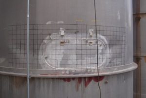
- Photographs of the Actual Shell Distortion
-
- Photographs of the Actual Shell Distortion
-
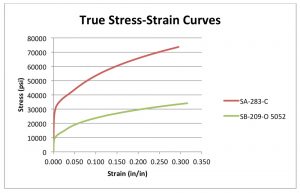
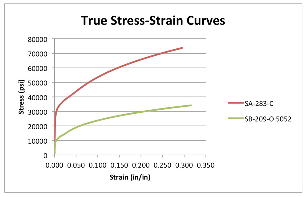
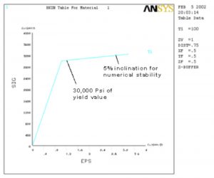
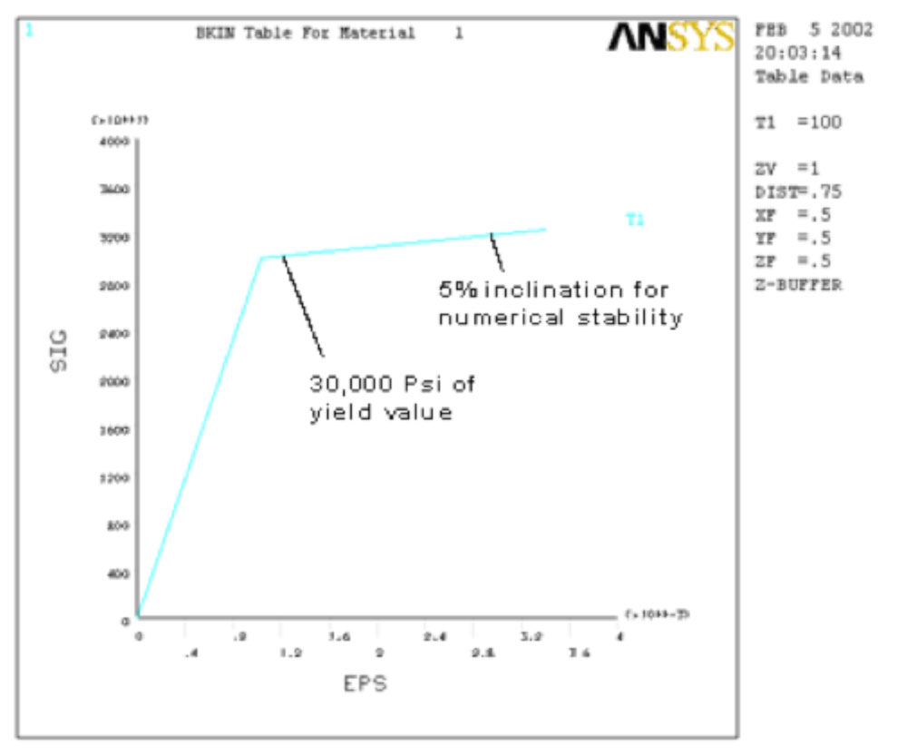
- True Stress-Strain Curves for the Materials
-
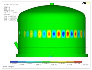
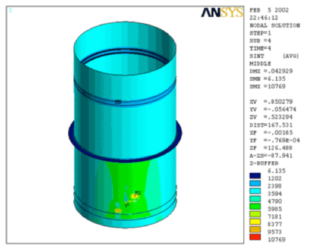
- First Local Buckling Mode Shape for Shell
-
- von Mises Stress Profile in Buckling Section

Buckling Analysis of a Tank
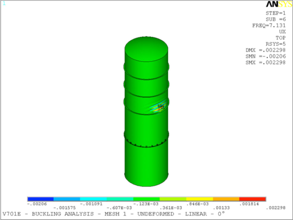
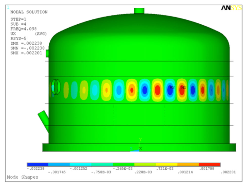
The scope of this analysis was to perform buckling analysis on a tank under the external operating pressure. Stiffening rings were added to the outside of the shell and the head to eliminate the buckling.
-
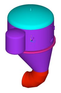
- General Layout for the Tank Without Added Stiffening Rings
-
- Tank with Stiffening Rings
-
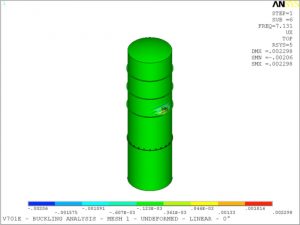
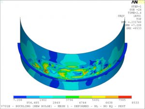
- Localized Buckling Mode Shapes
-

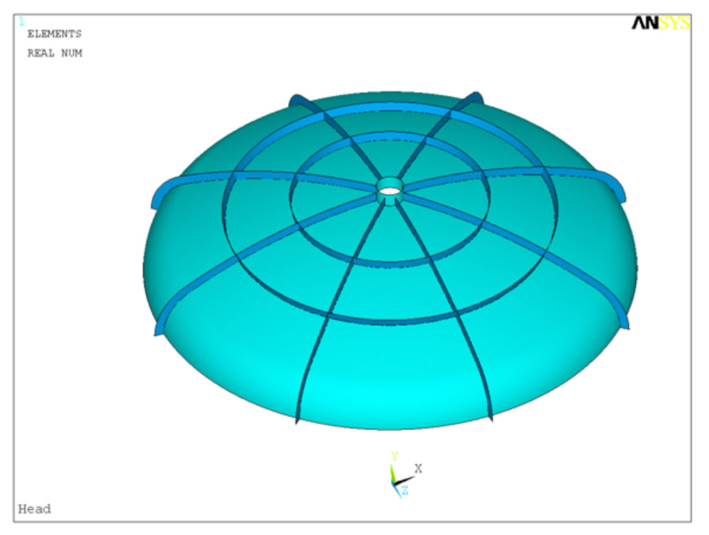
- Head with Stiffening Rings
-
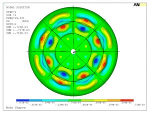
- Localized Buckling Mode Shapes

Non-Linear Buckling Analysis of a Process Column
A non-linear Finite Element Analysis (FEA) was performed to determine the possibility of a local and/or global structural buckling instability in a process column under a partial vacuum of -1.5 psig. A local area, with various thin sections, was investigated for possible failure during the operation of the column. The resulting stress intensities, strain, and deformation were analyzed using the general intent of ASME Section VIII, Division 2 code.
-

- Locations of Highest Stress in the Column Shell
-
- Locations of Highest Stress in the Column Shell
-
- True Stress/Strain Curve
Stress Analysis of a Furnace Stack Due to Over-Heating
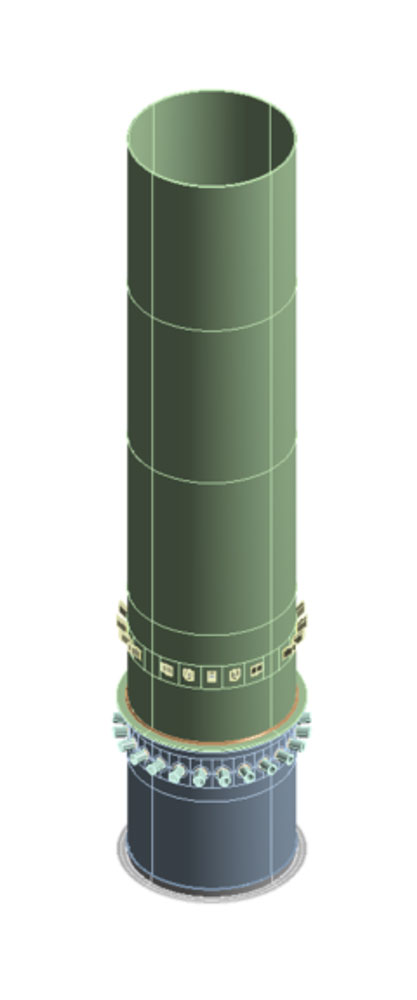
The scope of this analysis was to perform thermal and structural analyses of the furnace under their operating conditions. A three dimensional Finite Element Model (FEM) of the furnace was constructed and analyzed to verify the stress levels. 2015 ASME Section VIII, Division 2, Part 5 was used as a guide to perform the analyses.
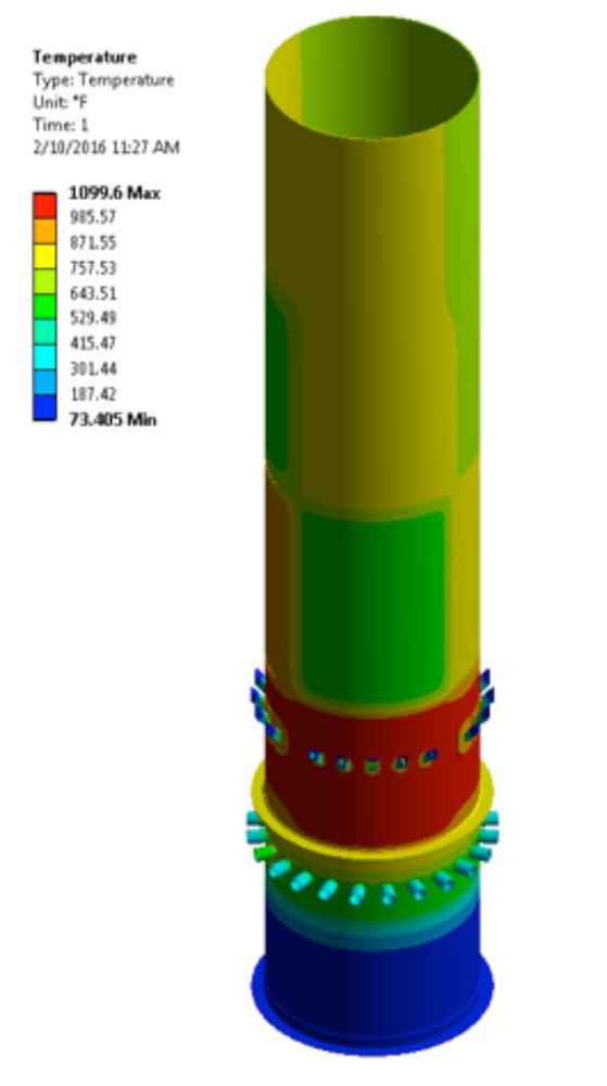
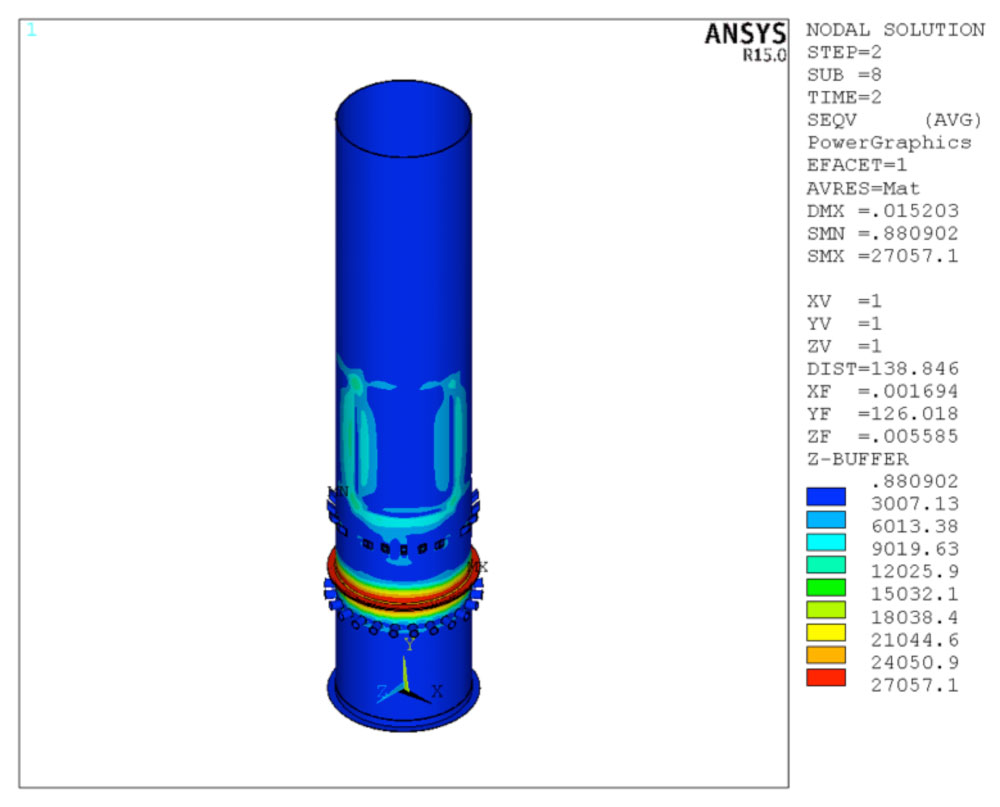
The thermal model included all the relevant components required for the complete thermal stress analysis. The convection coefficients were applied to the interior and exterior surfaces of the components. An initial analysis indicated the radiation effects were substantial compared to the convective heat transfer coefficients. Therefore, surface to ambient and surface to surface radiation phenomenon was also considered to achieve the desired temperatures on the cooling jacket as reported in the field data. The temperature distribution resulting from these thermal analyses were then used in the structural analysis as body loads. Structural Finite Element Analyses (FEA) was performed using the load combinations prescribed in ASME Section VIII, Division 2, Part 5 to determine the stresses in the vessel.
-

- General Layout of the Furnace
-
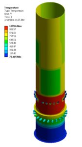
- Temperature Profile
-

- Residual Stress Distribution in the Furnace After Cooldown
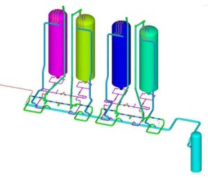
FEA Analysis of a Round Reformer with 4 Pulsating Gas Heaters
Finite Element Analysis (FEA) was performed on a vertical reformer. Shell elements were used to model the reformer body and the attached nozzles. Static analysis was performed considering the operating pressure and temperature of the reformer, the usage of different thickness and material for construction. The effects of wind, seismic, and gravity loadings were also considered in the FEA. After determining the adequacy of the design, based on ASME Section VIII, Division 1 and Division 2, modal analyses were performed to determine the natural frequencies and mode shapes of the structure. Subsequently, harmonic analysis was performed to evaluate the effect of dynamic loads during the operation of the reformer. Coupled thermal-structural analysis was also performed to assess the effects of thermal stresses on the nozzles with high temperature gradients.
-
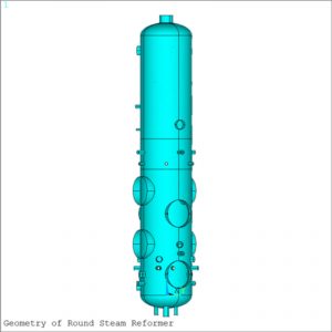
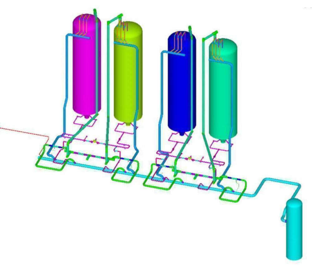
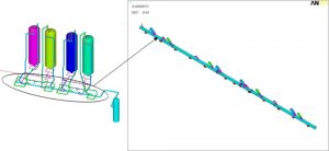
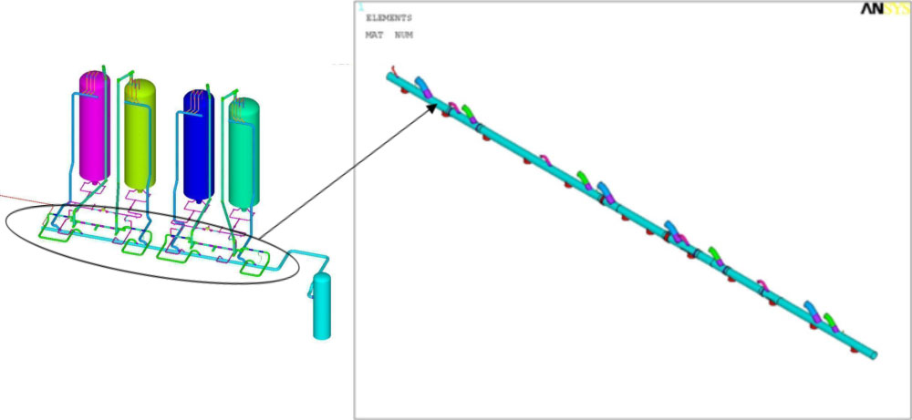
- Geometry of the vertical steam reformer – The Finite Element Model (FEM) is meshed using ANSYS 4 node “shell181” elements with 6 degrees of freedom at each node (3 rotational and 3 translational degrees of freedom).

-
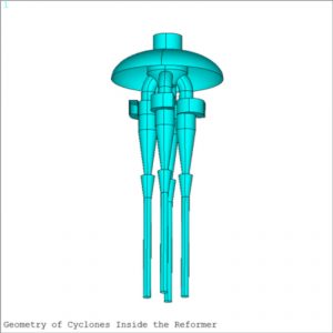
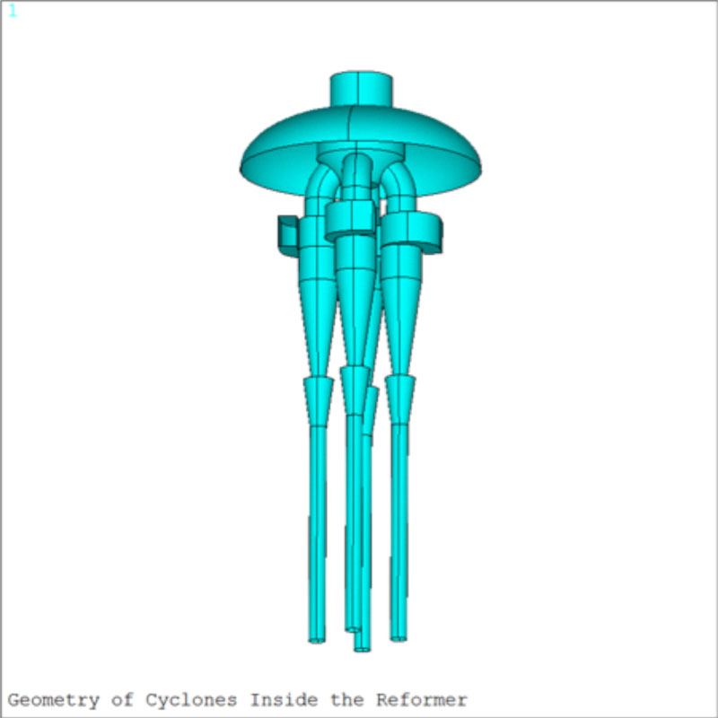
- Four cyclones were also considered in the FEM and connected to the inside of the top head.
-
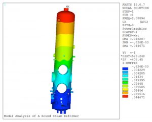
- Modal analysis was performed on the reformer considering a fixed support at the bottom tangent line. The natural frequencies of the first five mode shapes of the reformer were obtained from the analysis. The figure above illustrates the mode shape for the fundamental natural frequency of the reformer determined to be 3.80 Hz.

-
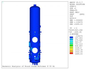
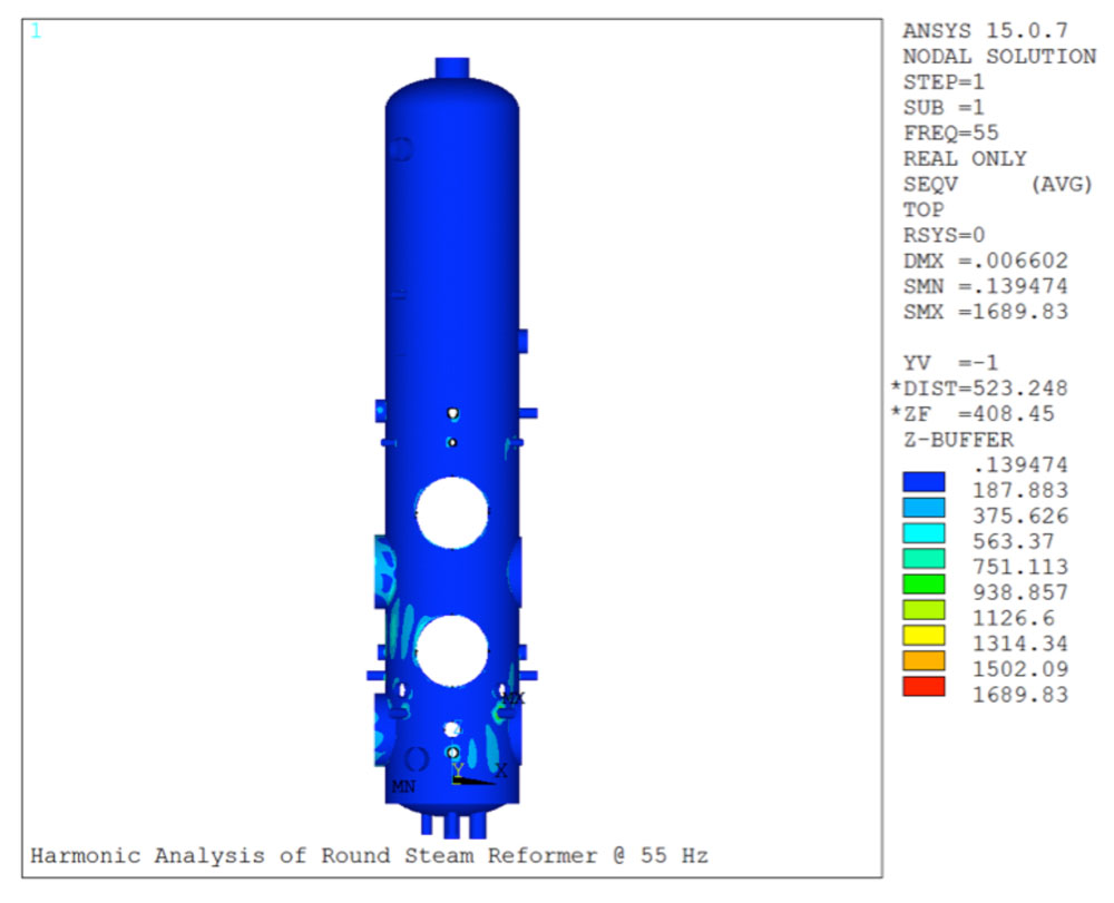
- The figure shows harmonic analysis performed on the round reformer at 55 Hz. The dynamic loads applied at this frequency range were related to the vibrations in the heaters. The maximum Von Mises stresses caused by these dynamic loads are observed around the heater elevations.
-
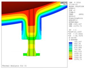
- The figure shows thermal analysis performed on one of the nozzles at the bottom of the reformer, which has an inside temperature of 1400°F. Based on the refractory setup inside the nozzle and reformer shell, and the conductivity properties of different materials in that location, the temperature decreases to approximately 350°F at the reformer-nozzle junction.

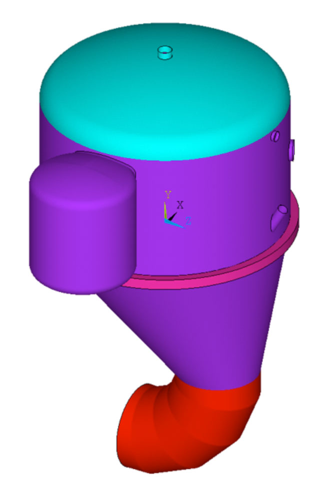
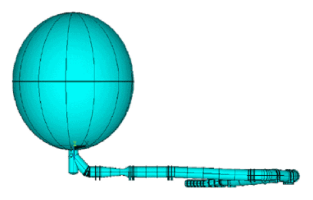
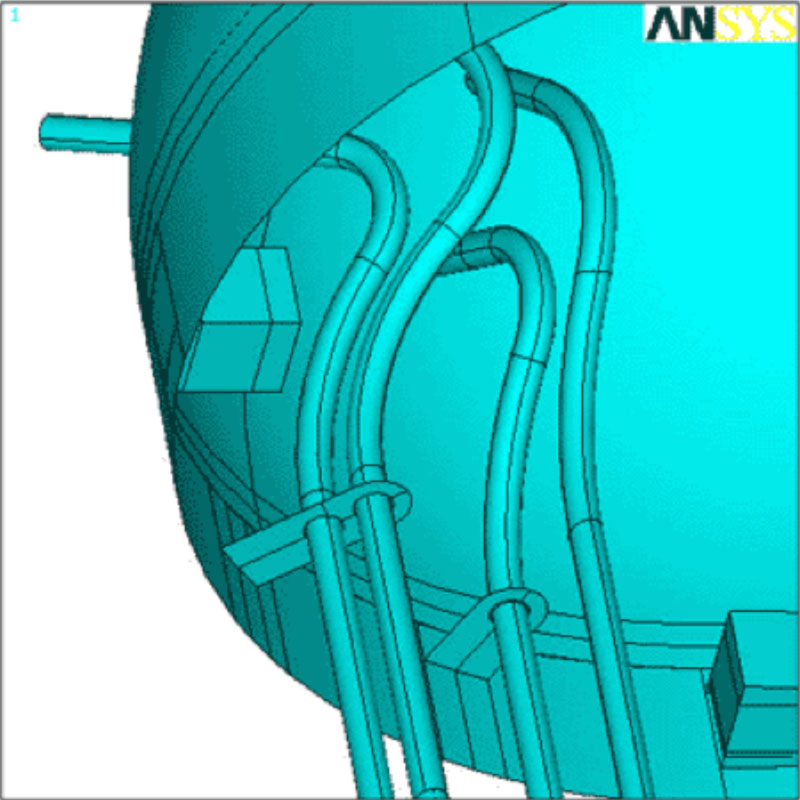
Nonlinear Buckling & Fatique Analysis of a Large Diameter Sphere & Its Complex Ductwork Under Transient External Pressure (MODEL)
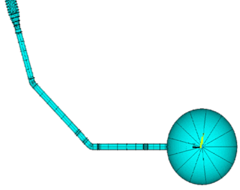
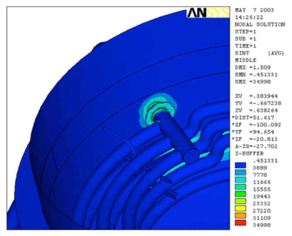
In 2001, Openso Engineering was involved in a project with Northrop Grumman Space Technology (formerly TRW), U.S. Air Force, and Lockheed Martin for development of the YAL-1A Airborne Laser (ABL) system. Openso’s responsibility included performing nonlinear buckling and fatigue analysis of a large diameter sphere and its ductwork under transient external pressure. The sphere and ductwork were part of the recharging equipment for a modified Boeing 747 aircraft equipped with a chemical oxygen iodine laser.
-

- Top Down View of Chemical Oxygen Recharging Equipment
-

- Elevation View of Chemical Oxygen Recharging Equipment
-
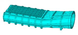
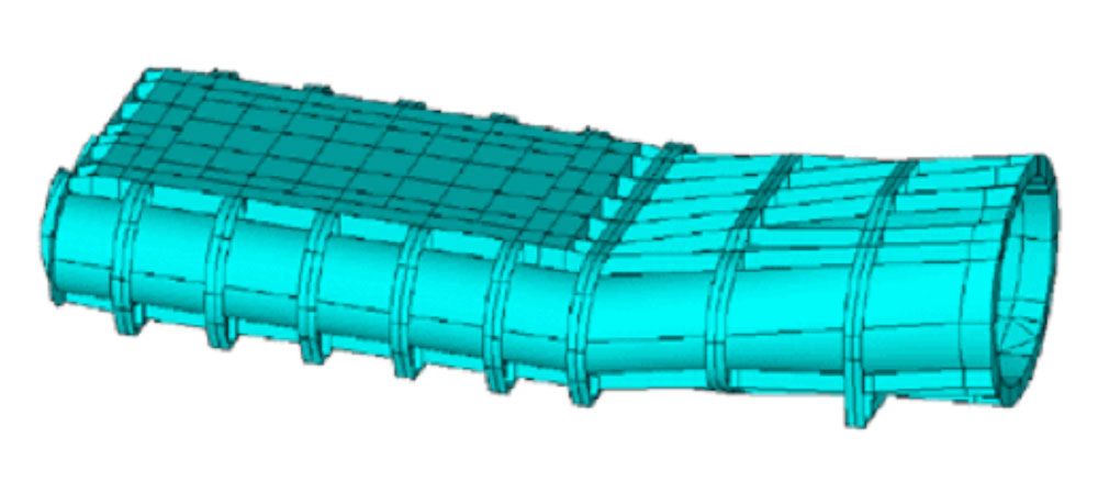
- Ductwork for Chemical Oxygen Recharging Equipment
-
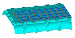
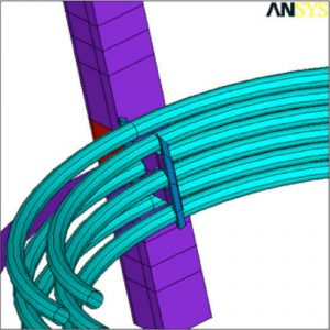
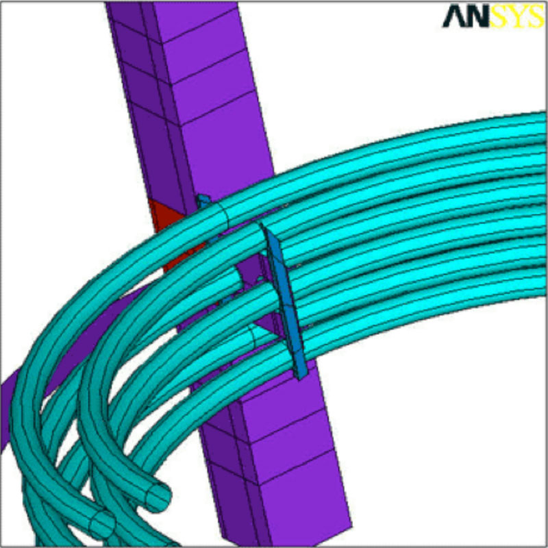
- Loads on the Ductwork for Chemical Oxygen Recharging Equipment
Failure Analysis of Flanges and Supports
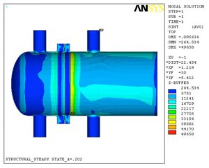
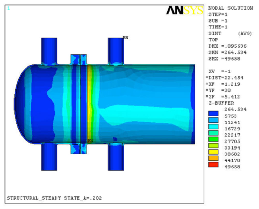
A Finite Element Analysis (FEA) was performed in support of a failure analysis of the cracks/failure of the flanges, supports, and fillet welds using brick elements. The Finite Element Model (FEM) consisted of nozzles, saddles, tube-sheets, body flanges, tubes, relevant tube side heads, shells, and inlet channels. A thermal stress analysis was performed to determine the state of stresses. The state of stresses was used in determination of the fatigue life of the area of concern.
-
- Geometry of the Finite Element Model
-
- Temperature Distribution of Heaters

-

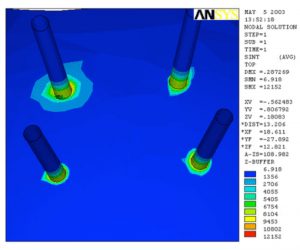
- Stress Intensity Levels at the Supports
-

- Rotation of the Body Flange and Tube-sheet
-
- Enlarged view of the Rotation at Body Flange
-
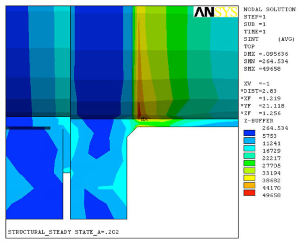
- Stress Intensity in the Fillet Weld Connecting the Tube-sheet and Shell
-

- Enlarged View of the Fillet Weld Connecting the Tube-sheet and Shell
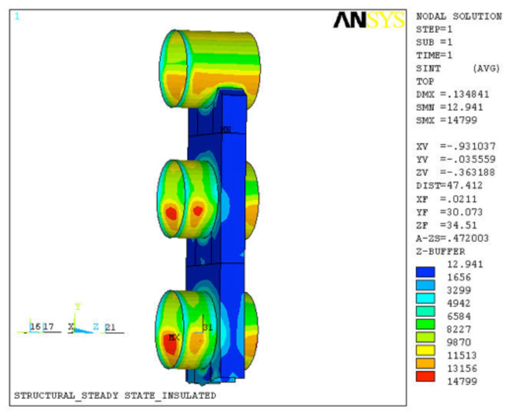
Finite Element Analysis/Fatigue Analysis of Three Vessels Interconnected With a Complex Piping System
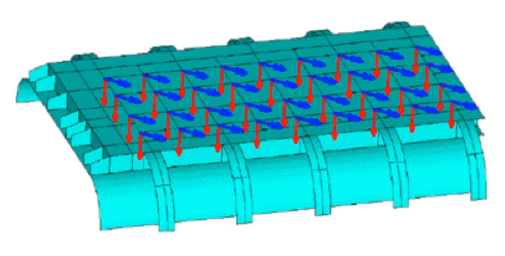
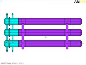
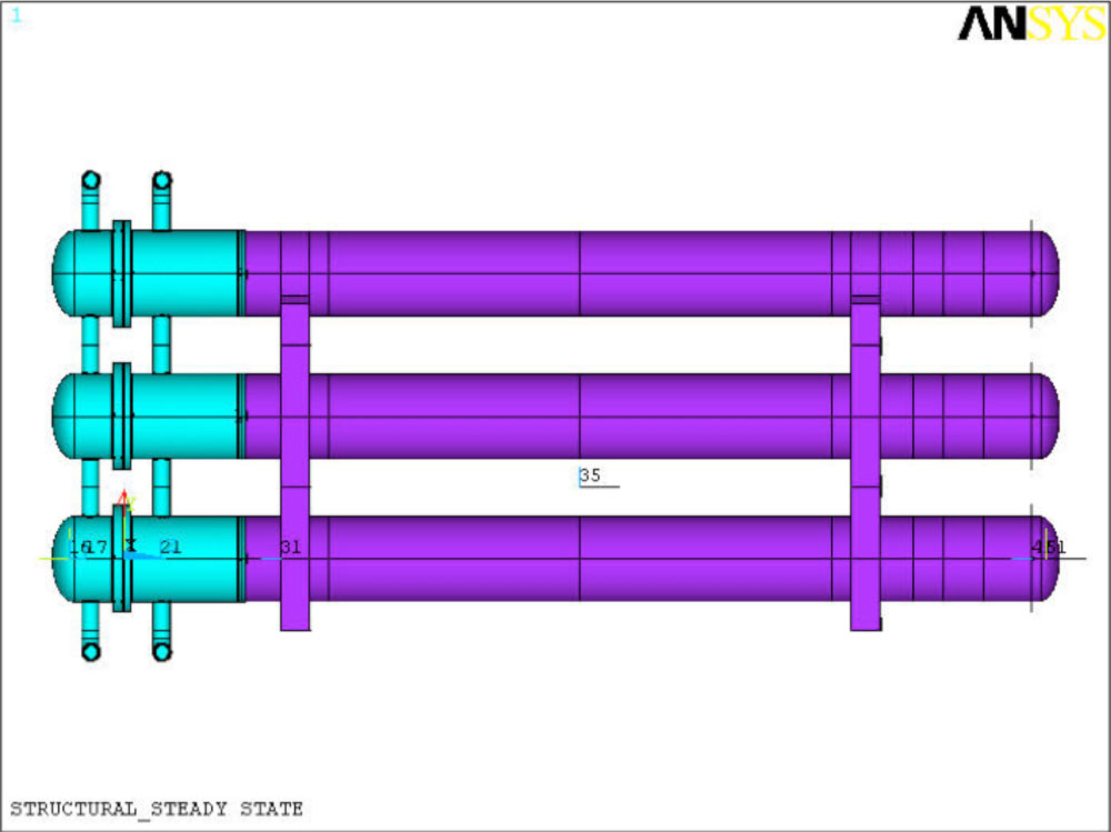
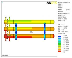
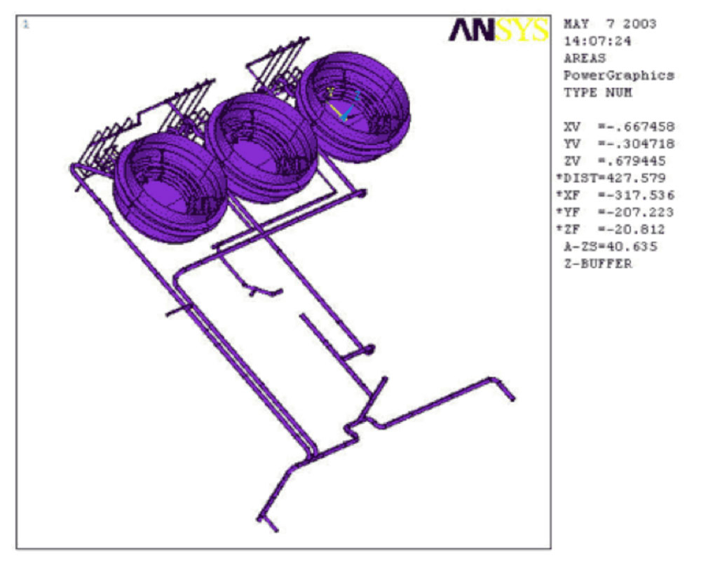
A 3D Finite Element Analysis (FEA) was performed for three vessels, their internal coils, and their interconnecting piping systems. The operating condition of the reactors includes the effects of the internal vessel pressure, internal coil pressure, thermal gradients, agitation loads, and gravity forces.
-

- Plan View of Three Vessels with Piping Attached
-
- Stresses of Pipe Nozzle Attachment to Shell Wall
-
- Stresses of Pipe Nozzle Attachment to Shell Wall
-

- Stresses of Pipe Nozzle Attachment to Shell Wall
Design and Analysis of New Dryer Scrubber
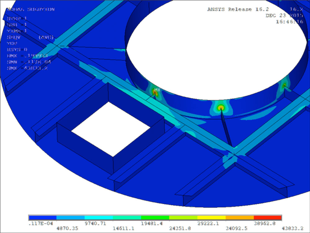
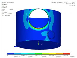
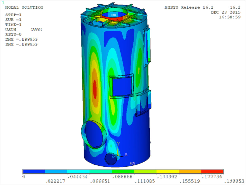
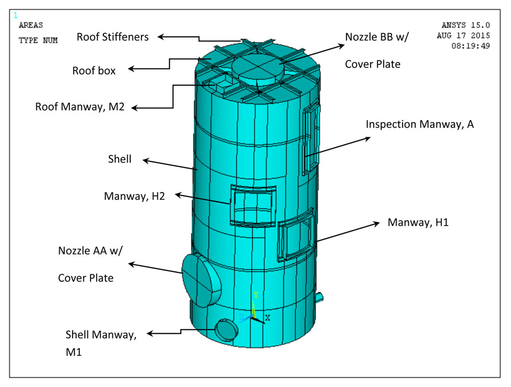
The scope of this project was to design and analyze a New Dryer Scrubber with the following design conditions: atmospheric pressure -35” of water column partial vacuum at 230ºF plus max liquid level of 4’-8”. The tank and nozzles of the Scrubber were designed per API 650. The preliminary tank design was based on longhand calculations, and then analyzed using Finite Element Analysis (FEA) to verify the adequacy of the tank under the design conditions (nozzle loads and wind/seismic loads were provided by the customer).
-
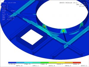
- von Mises Stresses at the Outlet Nozzle on the Tank Roof. Max Stress Occurs at the Junction of the Web Plate and the Nozzle Neck.
-
- von Mises Stresses at the Inlet Nozzle on the Tank Wall. Max Stress Occurs at the Junction of the Nozzle Neck and the Tank Wall.

-

- Maximum Displacements can be Seen at the tip of Outlet Nozzle on the Roof and Midway up the Tank Wall.
-
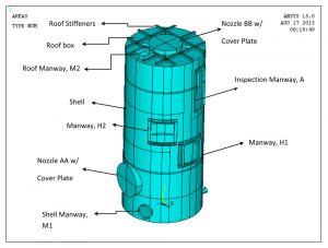
- Replacement Scrubber Tank per API 650
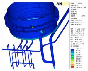
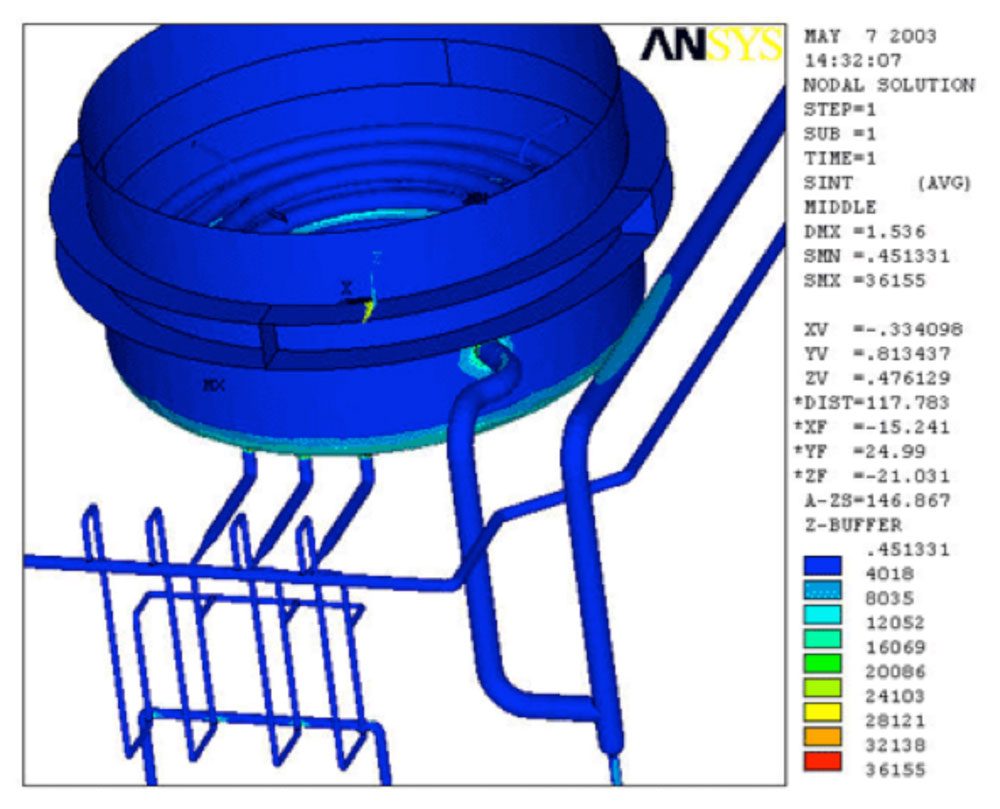
Finite Element Analysis/Fatigue Analysis of Reactor and its Internal Coils
A 3D Finite Element Analysis (FEA) was performed for the top head and internals of a reactor. The operating condition of the reactor included the effects of internal pressure, temperature gradients, agitation loads, and gravity forces.
-
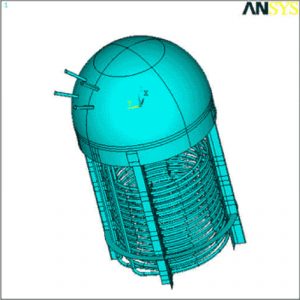
- Layout of the dome and Internal Coils
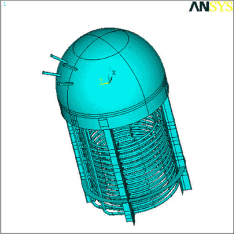
-
- Layout of the dome and Internal Coils
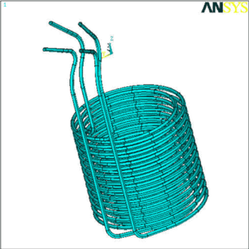
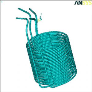
-
- Layout of the Internal Coils and Piping
-
- Layout of the Internal Coils and Piping
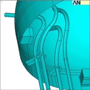
-
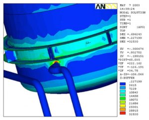
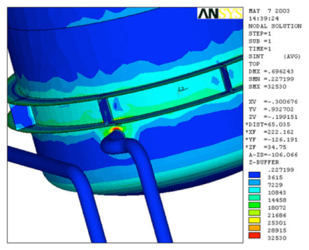
- Stress on Coil to Dome Penetration

-

- Stress on Internal Coil Support
-

- Layout of the dome and Internal Coils