Flange Misalignment Analysis of Heat Exchangers and Piping System
Openso was requested to determine potential factors causing misalignment in a heat exchanger and associated piping system. The misalignment was determined to be caused by the thermal expansion and contraction of the piping system relative to the flanges of the heat exchangers. The accumulation of plastic strain, and therefore permanent deformation at weaker sections of the piping resulting from thermal expansion, was instrumental in the formation of the total misalignment.
-
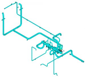
- General Layout for the Piping System

-
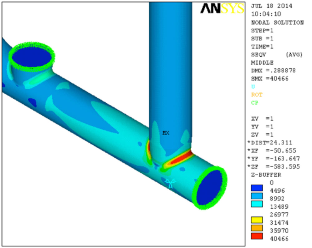
- Total Misalignment in the Piping Flange to Pump Connection
Field measurements, design, analysis, and Isometric Drawing Production for Expanding a Chlorine Abatement Unit
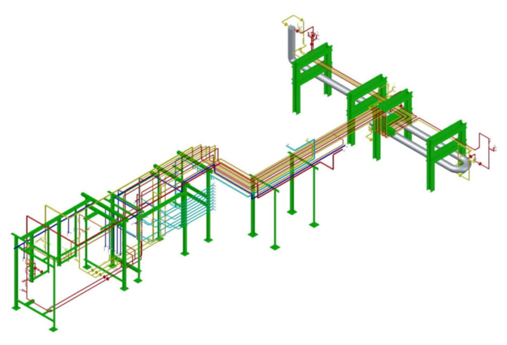
Field measurements were performed for a new chlorine abatement unit pipeline route in order to expand production for a chemical company. Initial pipe routing sketches for natural gas, hydrogen, chlorine, and nitrogen lines were modeled using AutoCAD Plant 3D. Pipe supports were also included in the 3D model for each pipeline from the customer interface point to end user. The routing information, types of valves, switches, instrumentation, and supports were included in the isometric drawings. Pipe stress analysis was performed based on ASME 31.3 to determine the adequacy of the supports using CAESAR-II.
-

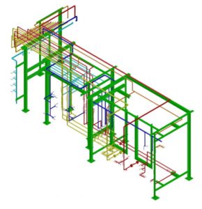
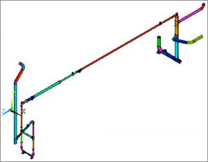
- Chlorine Abatement Unit Model with Nitrogen, Natural Gas, Hydrogen, and Chlorine Pipe Routes with Valves, Instrumentations, and Supports
-

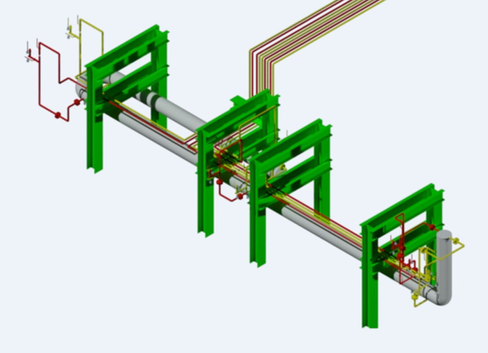
- Injection Ring Inlet of the Chlorine Abatement Unit
-
- Metering and Switching Station Modeled for the Chlorine Abatement Unit

-
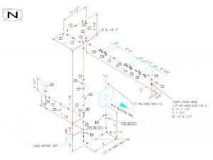
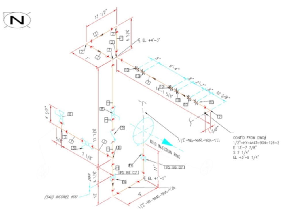
- Isometric Drawing of the ½” Hydrogen Line to the Injection Ring
-
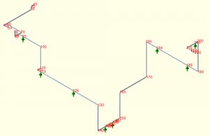
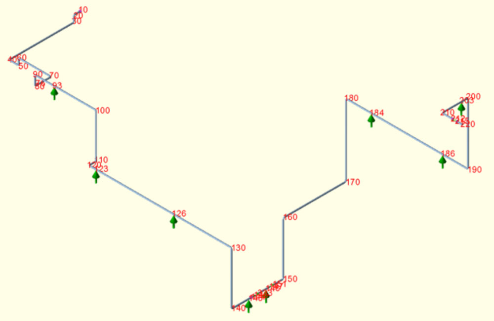
- CAESAR-II Pipe Flexibility Analysis for one of the Pipelines in the Chlorine Abatement Unit
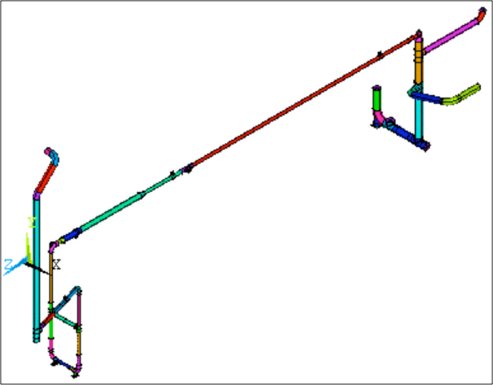
Distilling Piping Replacement – Fitness for Service Analysis
A Fitness for Service (FFS) analysis was performed to simulate the replacement of certain sections of the piping with stainless steel pipe. The following items were considered in the analysis:
- No future corrosion allowance was used for the new pipe sections; instead, 87.5% of the nominal wall thickness of the corresponding schedule of pipe was utilized to compensate for possible manufacturing tolerances.
- One pipe support was modified to model a new support style.
- All flanges in the model were checked to ensure compliance with ASME B16.5 and ASME Section VIII, Division 1 codes for flange stresses.
-
- Overall View of the Geometry
-
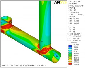
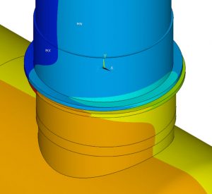
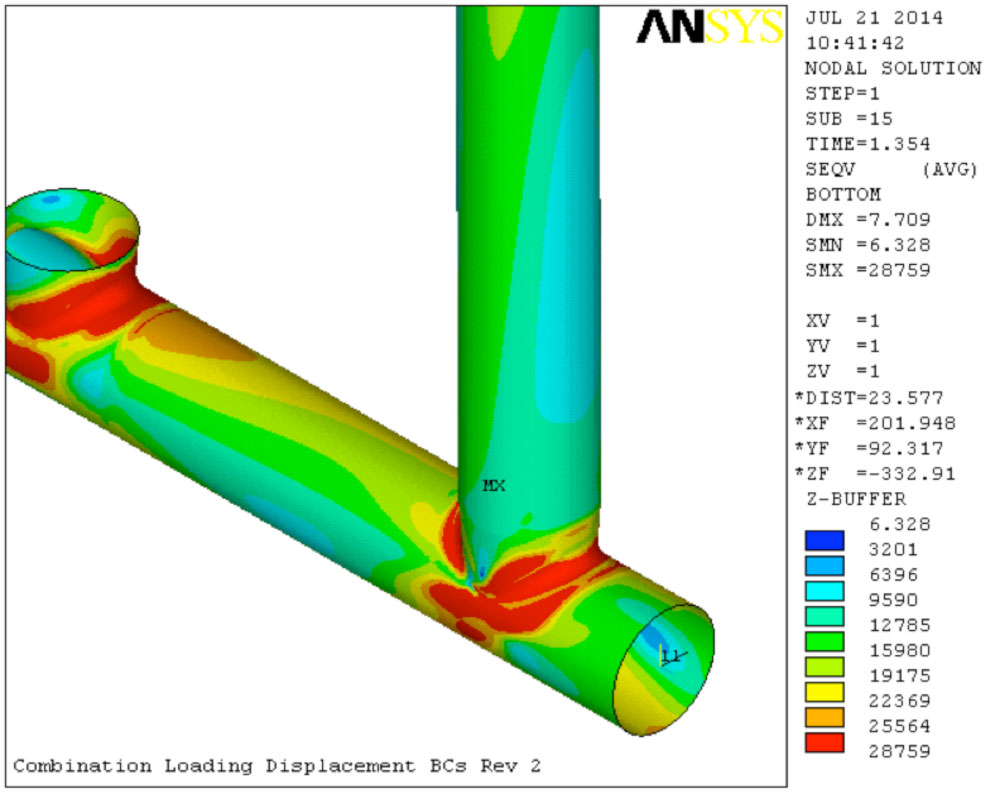
- Locations of Highest Von Mises Strain
-

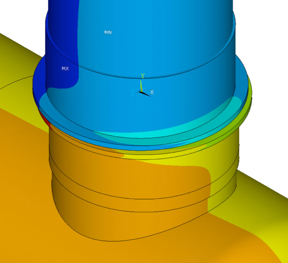
- Location of Highest Von Mises Stresses