One of our customers experienced extensive cracking in their blowdown header of their hydrocarbon blowdown system. The blowdown header was fabricated from 36” Schedule 40 pipe. The thickness of the blowdown header varied between 3/8” to 3/4” thick along the length.
-
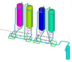
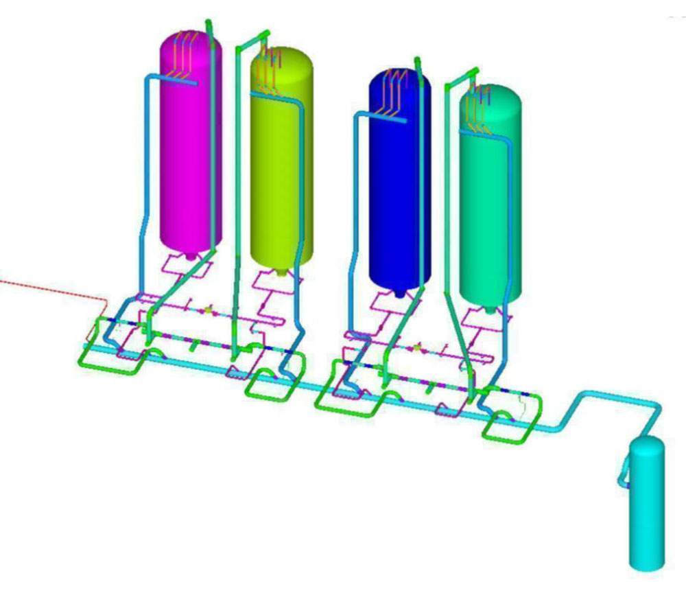
- General Layout of the Coke Drums and the Associated Blowdown System
-
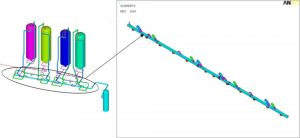
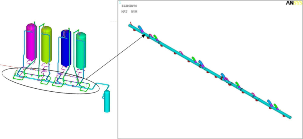
- Section of the Blowdown Header Where Most of the Crack-Like-Flaws Were Observed
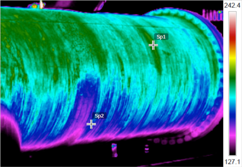
IR thermal images of the blowdown header were taken during operation to assess the temperature distribution in the piping. Thermocouples were also installed to record the temperature of the blowdown header at different locations. Based on the thermal images and thermocouple readings, it was determined that a significant temperature gradient was present in the circumferential direction of the header at various stages of the operating cycle.
-
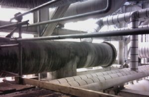
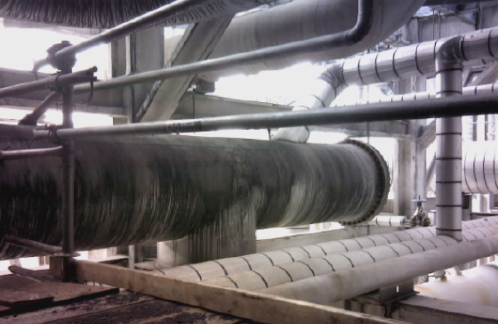
- Photograph of Blowdown Header
-

- IR Thermal Image of Blowdown Header
The crack-like-flaws were circumferential and approximately straddled the centerline of the header (6 o’clock position). The crack-like-flaws seemed to initiate from the inside surface of the header propagating radially outward.
The crack-like-flaws were observed during routine inspection. Two holes were drilled through the header at the ends of the crack to arrest future crack propagation. This was done in preparation for clamp installation. When the holes were drilled, a significant amount of liquid hydrocarbon drained from the header. This indicated that a pool of residual liquid hydrocarbon remained in the pipe, and had not properly drained from this location. This residual liquid was determined to have a significant effect on the life expectancy of the blowdown header.
-
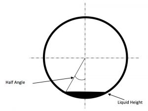
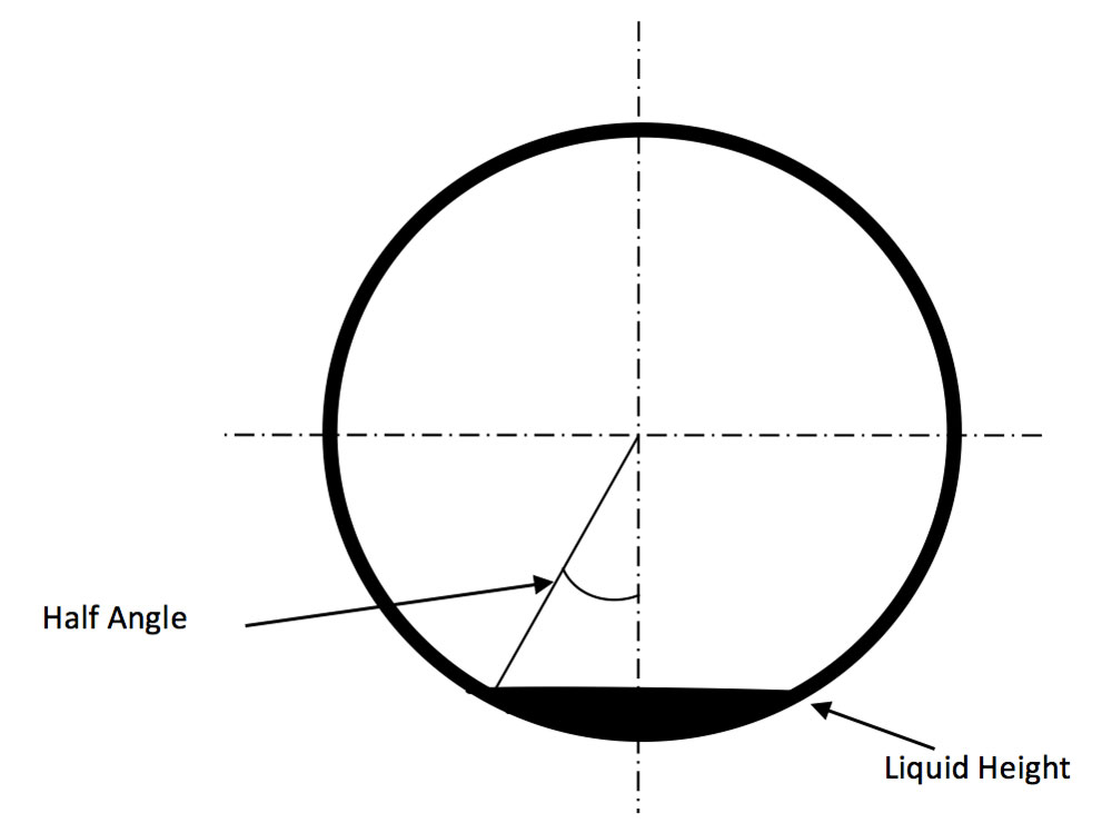
- Representation of the Liquid Hydrocarbon Pooling in the Blowdown Header
-

- Blowdown Header Internal Layout

The blowdown system was analyzed using Computational Fluid Dynamics (CFD), Finite Element Analysis (FEA), and pipe stress analysis. The boundary conditions used for the analyses were provided by the customer for a typical operating cycle. An operating cycle was defined as each of the four Coke drums filling, quenching, draining, and drilling.
*NOTE: Insert animation here for the cycle described above (File “Transient 3 Cycle Oblique”)*
The circumferential thermal gradient caused a differential longitudinal growth between the upper and lower regions of the header. This caused the longitudinal membrane stress of the upper region to be in compression, while the lower region was in tension. Due to the relative size of the lower region compared to the upper region, the stress level in the lower region was significantly greater than the upper region. In addition, the thermal gradient caused ovalling of the header. The ovality of the header was observed to be maximum at locations with relative greater stiffness, such as nozzle to header junctions. The ovality was intensified at the thicker transitions due to the large change in stiffness between the 3/4” and 3/8” thick sections.
-
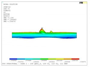
- Ovalling-Blowdown-Header-Due-Thermal-Stresses

Additionally, fatigue analysis calculations were performed for the locations with lowest and greatest life expectancies. Fatigue analysis was also performed for the sections of the blowdown header at locations with locations with hydrocarbon liquid accumulations. The calculations were performed for a welding residual stress of 48 ksi since no Post Weld Heat Treatment (PWHT) was performed. It was determined that the weld quality had a significant impact on the life expectancy of the blowdown header welds. Fatigue calculations were performed in accordance with the latest ASME Section VIII, Division 2, Part 5.5.5.
The following analyses were performed:
- Calculation of thermal boundary conditions (analytical method)
- Calculation of thermal boundary conditions (CFD)
- Intended normal operating condition for original design
- Effect of circumferential thermal gradient on life expectancy
- Calculation of liquid level in blowdown header (includes evaporation)
- Effect of liquid level on circumferential thermal gradient
- Effect of insulating the blowdown header on life expectancy
- Effect of thickness transitions on life expectancy
- Potential long-term repair for blowdown header
Thermal stress analyses of the blowdown header were performed using ANSYS® Finite Element Analysis (FEA) software. A Three-Dimensional (3-D) Finite Element Model (FEM) was developed to perform the analyses. All parts of the hydrocarbon blowdown system were included in the FEM. The element type used for each major component in the model is described below. The element types are provided for both the thermal and structural analyses that were performed.
- Piping, vessels, supports (other than spring and hanger type supports)
- Structural – SHELL181, 4-node, 3-D solid element with six degrees of freedom per node: translations and rotations in x, y, and z directions.
- Thermal – SHELL57, 4-node, 3-D solid thermal conduction element with one degree of freedom per node: temperature.